Proteco BARRY Manuel utilisateur

AUTOMATIC ROAD BARRIER
BARRY
User Manual
02_18


Index
1. WARNINGS AND INSTALLATION TIPS ..................................................................................................................... p. 01
COMPLIANCE DECLARATION ................................................................................................................................. p. 01
2. TECHNICAL FEATURES ............................................................................................................................................. p. 02
3. INSTALLATION .......................................................................................................................................................... p. 02
3.1
3.2
3.3
Standard layout
Basement preparation
Fixing the barrier on ground
4. MANUAL OPERATION .............................................................................................................................................. p. 03
5. LOCK AND UNLOCK THE TOP COVER ................................................................................................................... p. 03
6. BALANCING OF THE BOOM ................................................................................................................................... p. 04
7. LIMIT SWITCHES ....................................................................................................................................................... p. 05
8. MAIN POWER ........................................................................................................................................................... p. 05
9. AC WIRING DIAGRAM (230/115Vac) ................................................................................................................... p. 06
10. DC WIRING DIAGRAM (24V DC) ........................................................................................................................... p. 08
11. ADDITIONAL DEVICES ............................................................................................................................................. p. 10
11.1 PHOTOCELLS in CLOSING
11.2 Loop detector (contact N.C.)
11.3 Loop detector (contact N.O.)
11.4 START commands............................................................................................................................................................ p. 11
12. RADIO PROGRAMMING ......................................................................................................................................... p. 11
12.1 Transmitter storage
12.2 Deleting all transmitters

1
1. WARNINGS AND INSTALLATION TIPS
This manual contains important information concerning personal safety. An incorrect installation or an improper use may lead to
severe injuries. Read carefully and store for future use.
Pay particular attention to this symbol.
Switch the power OFF before any operation.
Double check the electrical grounding and fit a disconnection device as well as overcurrent protection.
Keep the remote controls away from children.
• Use <HAR> wires/cables, minimum section 2 mm².
• Do not alter the original internal wiring.
• If power cut occurs, turn the power off and only then proceed to open and release the system.
• Give any start command only if the system is visible.
• Do not open the barrier housing when the system is operating.
• Do not allow children to play within the system area.
• Fixed start commands must be positioned at a minimum height of 1,5 m from ground.
The installation of automatic doors and gates must comply with the Machine Directive 2006/42/CE, in particular with EN 12453
provision.
The definitive connection to the power supply, as well as testing and starting shall be performed by qualified personnel, who will be
held to check risks and ensure the system complies with the current regulations.
This product has been designed only for its intended use. Any other use could affect the integrity and safety of the product, therefore
has to be considered prohibited.
Use only original spare parts. No alteration on the system has to be carried out. Proteco Srl will not respond in case of using additional
and/or fake spares.
Automatic barriers are not suitable for pedestrian clearance.
BARRY is designed for vehicular clearance only.
CE COMPLIANCE DECLARATION
Manufacturer:
Address:
Declares
The Product:
Type:
PROTECO S.r.l.
Via Neive, 77 – 12050 Castagnito (CN) – ITALIA
BARRY Automatic Road Barrier
BARRY 230V, BARRY DC 24V
Complies with the essential requirements of EEC Directives:
2014/35/UE Low Voltage Directive
2014/30/UE Electromagnetic Compatibility Directive
2014/53/UE RED Directive
It complies, where applicable, with the following provisions:
EN 61000-6-2, EN 61000-6-4
EN 61000-3-2, EN 61000-3-3
EN 12453
EN 60335-1, EN 60335-2-103
The manufacturer declares that the start-up of the machinery is not permitted unless the machine, in which the product is incorporated or of which
is becoming a component, has been identified and declared as conformed to 2006/42/EC Machinery Directive.
Castagnito, 2018 November 8th Marco Gallo
CEO
RoHS2 2011/65/CE

2
230V AC 24V DC
2 TECHNICAL FEATURES
3. INSTALLATION
3.1 Standard Layout
Look at the beside layout and keep a safety distance of
500 mm each side.
The length of the boom will be accordingly,
but the concrete basement position is fixed.
3.2 Basement preparation
The concrete basement must be resisting (EN206 C25/30
minimum resistance). Basement plant has to be at least
400x500 and 600 mm deep.
Keep a projection of 20 mm from the ground floor to
ensure stability.
In any case the concrete work cannot impede to stud
the fixing screws.
Do not forget wirings! While preparing the
concrete basement keep a duct of the right
dimension to connect the main power and any
additional devices, if needed.
3.3 Fixing the barrier on ground
Drill the concrete basement, put the screws provided and fix the barrier body:
230V 50Hz
230V ac
200W
1,5A 230V
circa 6 secondi
da 1 a 60 sec.
6m
12Vdc, 8W max
da -20 a +50 °C
433,92 MHz
Main power:
Motor power supply:
Motor power:
Absorption max.:
Opening time:
Automatic closing:
Boom max. length:
Accessories:
Working temperature:
Radio frequency:
230V 50 Hz
24V dc
160W
1,2A 230V
circa 6 secondi
da 1 a 60 sec.
6m
24Vdc, 8W max
da -20 a +50 °C
433,92 MHz
Screws Basement
Metal housing
4 anchor screws M16
Ground plate
Boom from 1,5 to 6m

3
Pull the hand grip and turn
clockwise to unlock
Pull the hand grip and turn
counterclockwise to lock
For manual operation pull the hand grip and turn
clockwise.
Release the hand grip and move manually the boom.
During manual operation the boom could
suddenly lift up: be careful and always hold the
boom with your hands to avoid damages.
To lock the system, pull the hand grip and turn
counterclockwise.
Release the hand grip, now the barrier is locked.
When unlocking the barrier it is possible to adjust the
tension of the springs, set the limit switches, etc etc.
NB: In the 24Vdc version the manual operation can not
be done if the boom is fully raised.
5. LOCK AND UNLOCK THE TOP COVER
4. MANUAL OPERATION
Remove the top cover if adjustments are needed.
The cover is secured on the right by a fixed joint, while
on the left by a rotating tab, which can be unlocked
by a hand grip inside the barrier housing.
To remove the cover, unlock the rotating tab pulling
the hand grip towards the bottom, then lift the cover
from the left and disengage from the right upwards.
To reposition the cover, engage on the right and lower
the lid, then rotate the hand grip towards yourself and
turn the rotating tab to lock.
NB: Pls. consider that the hand grip, rotating tab and
fixed joint can be found in a different position,
according if the barrier is LH or RH.
Rotating tab
(lock and unlock)
Rotating tub Fixed joint

4
6. BALANCING OF THE BOOM
Size the boom length before installation: the boom is
modularized, cut or join according the length you need.
Fix the boom as shown in the picture.
Once the boom is fixed on the barrier and for any
reason the length has to be changed, proceed
to readjust the springs and the limit switches, in
the following way:
If the length has been decreased, the boom may
lift up a little bit, therefore proceed to reduce the
number of spring.
On the contrary if the length has been increased,
the boom may get down, therefore proceed to fit
both springs.
Look at the below table to fit correctly the springs
according to the boom length :
Boom length Springs Dimension
3 - 4 m 1 Ø 5,0 x 440 mm
4,5 - 5 m 2 Ø 4,5 x 440 mm
Ø 5,0 x 440 mm
6 m 2 Ø 4,5 x 440 mm
Ø 5,0 x 440 mm
Fit the springs, by number and type, following the
instructions shown here in the picture.
The tension of the spring has to be as much as to allow
to lift the boom safely and easily with your hand.
Once the springs have been adjusted, proceed to align
the boom when in horizontal position.
1 Loose the lock nut
2 Fix the position
3 Tighten the lock nut
1
Loose the
lock nut
2
Fix the position
Drive rod
and nut
Springs
Spring nut
3
Tighten
the lock nut
1
5
7. LIMIT SWITCHES
The barrier comes with both magnetic and mechanical
limit switches, pre-set by factory.
Normally it is not necessary to adjust them.
However if this were the case, see how to proceed as
shown in the below picture:
CLOSING position OPENING position
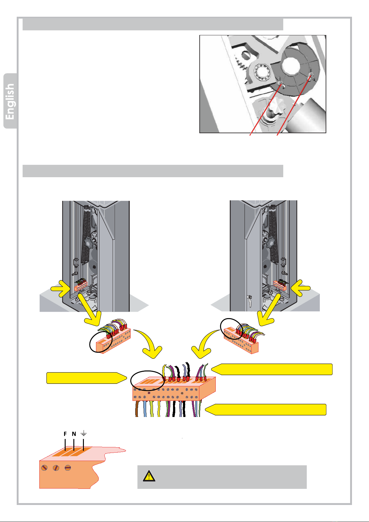
8. MAIN POWER (230V + GROUNDING)
The barrier can be powered both 230V and 115V AC, and main power has to be wired as shown in the below picture:
LH BARRIER - control unit positioned on the left RH BARRIER - control unit positioned on the right
Factory wiring
Main power
Factory wiring
Terminals are partially factory prewired, just wire Phase, Common
and Ground as shown below:
Always wire the GROUND!
The ground wire section has to be of the same
size of Phase and Common wires.

6
F1
K3 K6
K4 K5
F2
VR1 VR2
J1 J3 J7 J6
K1 K2
S3
OL CL PT LOOP POWER
PUSH
S5
LEARN
OPEN STOP CLOSE
T1
J9
OFF ON
OFF ON
1
4
2
3
5
6
11
10
9
12 8
7
S1
S4
9. AC WIRING DIAGRAM (230/115Vac)
Lights supply
Blinker
Limit switch OPEN
Limit switch CLOSE
Loop detector/Safety edge
Photocell CLOSE, N.C.
GND - Common
STOP push button N.C.
12V dc 8W max
START - STOP
Close
Open
LED WORK
LED WARNINGS
FACTORY WIRING
WIRING BY THE INSTALLER
1 = Transformer
2 = F1, fuse 0,2 A
3 = F2, fuse 5 A
4 = VR1, force
5 = VR2, automatic closing
6 = S1, DIP-switch terminals
7 = J2, aerial
8 = Receiver
9 = LEARN, transmitter storage
10 = Start commands
11 = Lights disconnector
12 = J9, obstacle detection (keep to ON)
The control unit comes from factory
with no. 2 bridges on N.C. contacts
Lights

7
VR1
VR2
S1
OL CL PT LOOP POWER
LEARN
OPEN STOP CLOSE
VR1 - FORCE
VR1 trimmer sets the force and the obstacle detection. Turning the trimmer clockwise the force
increases while the obstacle detection decreases. If J9 jumper is set right side (ON), the obstacle
detection will stop the barrier during closing and will reverse to opening position. Calibrate the
obstacle detection force properly, to avoid faults during normal operation.
VR2 – AUTOMATIC CLOSING
VR2 trimmer sets the automatic closing time (DIP-switch 2 = ON). The automatic closing time can
be adjusted between 1 and 60 seconds.
DIP-SWITCHES
DIP-switch 1:
ON - Set dip-switch 1 to ON if you need to wire a safety edge (the safety edge shall be wired
as well on terminal PT on the control unit).
OFF – Set dip-switch 1 to OFF if you need to wire a loop detector (the loop detector shall be
wired as well on terminal PT on the control unit).
DIP-switch 2:
ON - Automatic closing ACTIVATED (from 1 to 60 seconds.
OFF - Automatic closing DEACTIVATED.
DIP-switch 3: Void
LED Work
OPEN
STOP
CLOSE
LEARN
The barrier is opening
The barrier is in stand-by
The barrier is closing
Transmitter storage in progress
LED Warnings
OL
CL
Opening completed
Closing completed
PT
LOOP
Safety edge/loop detector operating
Photocells calibrated
POWER Barrier powered
Autres manuels pour BARRY
1
Table des matières
Autres manuels Proteco Système de contrôle


