PRODIM Proliner Manuel utilisateur

Measure it all!
Proliner Quick start guide
Training preparation

PRODIM 2017 © Proliner Quick start guide - Training preparation Page 2
General
Condential
The information contained in this Proliner Quick start guide – Training prepa-
ration is intended solely for the use of your company. You are hereby notied
that any disclosure, copying, distribution or taking any action in reliance of the
contents of this Proliner Quick start guide – Training preparation is strictly pro-
hibited and may be unlawful.
Copyright
© All rights reserved. Apart from the legally laid down exceptions, no part of
this publication may be reproduced, stored in an automated databank, or made
public in any shape or form, be it electronically, mechanically, by photocopying,
lming, or in any other manner, without prior written permission from Prodim
International BV in Helmond (NL).
Disclaimer
The inuence of the operator on the measuring process is dominant, thus making
him fully responsible for accuracy and safety. While using the Proliner he must
ensure that:
No one is allowed near the cable or the control box while the pen is in use. A
broken cable or dropped pen can cause rapid and unpredictable retraction of
the cable which can severely injure anyone it might contact.
We advise to make control measurements once in a while to ensure accuracy.
The Proliner is a precision measuring machine. Let only trained personnel
work with the Proliner. Do not use the Proliner in areas where there is a lot of
construction work.
Subject to change
The contents of this manual may change without notice.
Proliner® is a registered brand name of Prodim International BV.

PRODIM 2017 © Proliner Quick start guide - Training preparation Page 3
Index
Package Contents 4
The Proliner (hardware) 5
The remote control 6
Proliner menu (software) 7
2D Projection 9
Measurement compensation 10
Positioning 11
Leap function 12
Measuring in 5 steps 13
Proliner CT 14
Maintenance 15
Chapter 1
Chapter 2
Chapter 3
Chapter 4
Chapter 5
Chapter 6
Chapter 7
Chapter 8
Chapter 9
Chapter 10
Chapter 11
Video’s:
Each chapter contains a video providing a visual explanation of the content.
Important! You have to enable captions to be able to view the video instructions:
• Open the video from this guide
• Click on YouTube or to enable captions
If desired, you can choose another language in YouTube.
Have fun measuring!
Before you start:
This Proliner quick start guide explains the components and basic operations of a standard Proliner package. This
guide is applicable for each Proliner type. The examples mentioned in this guide can dier from your situation,
because we supply tailored packages (for both hardware and software) to each customer’s needs.

PRODIM 2017 © Proliner Quick start guide - Training preparation Page 4
1. Package Contents
Standard parts of the Proliner package:
1x Proliner 1x remote control 2x battery
1x battery charger 2x adapter with cable 1x bag with tracers
1x USB stick 1x Prodim touchscreen pen 1x cleaning cloth
Forms
Watch the video
ATTENTION!
Check your packing list for the exact content of your order / package.
The content may dier from what is shown here. Contact Prodim if the
supplied content deviates from packing list.
1x Bluetooth-USB-dongle
PRODIM 2017 © Proliner Quick start guide - Training preparation Page 5
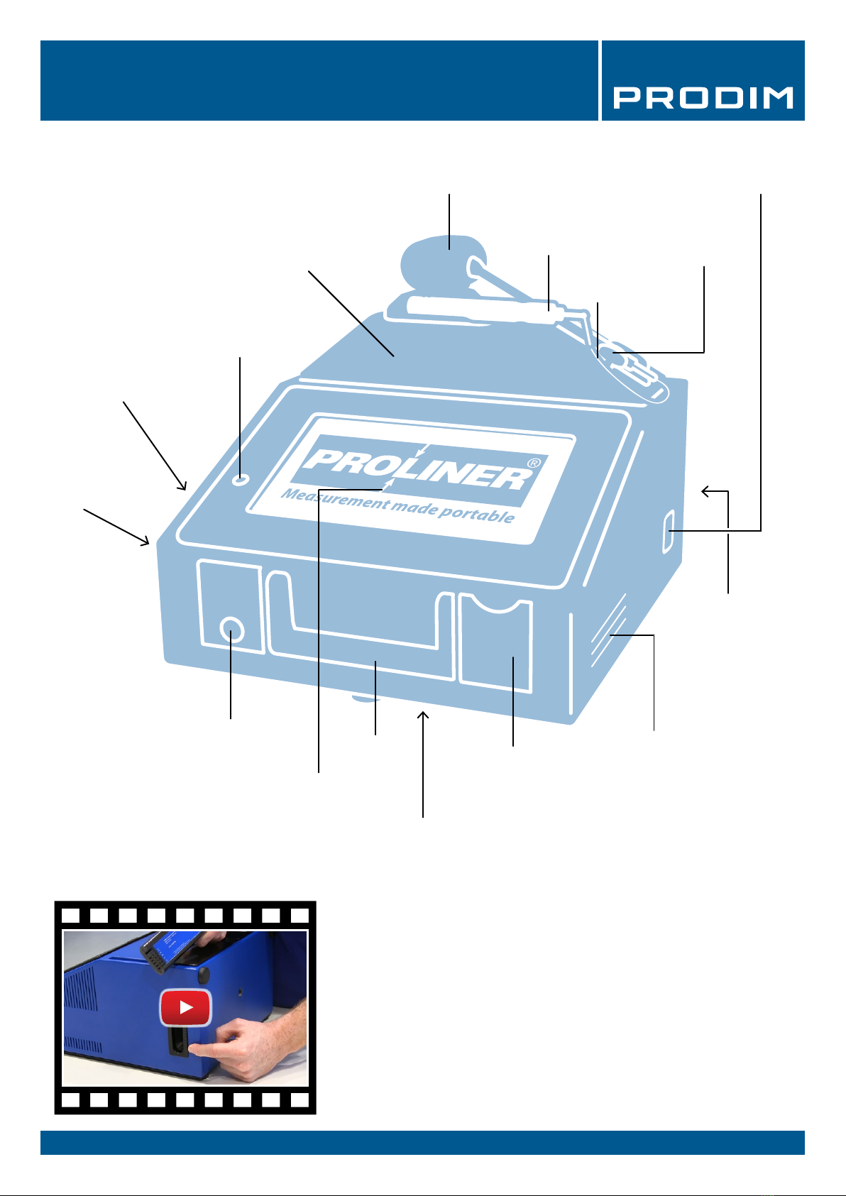
2. The Proliner (hardware)
Touchscreen
Carrying
handle USB port
Data port (Ethernet)
Power connection
Ventilation grid
Battery
connection
Rotatable measuring head
Measuring pen
Measuring wire
Measuring head
unlock button
Storage drawer button
Power button
Foldable measuring unit
Signal speaker
Proliner parts:
Storage drawer
Watch the video
Screw mount
(back side)
Screw mount
(bottom)
TIP: Mount the Proliner on a tripod for a better reach!
Screw mounts can be used to attach the Proliner on a tripod.
They are positioned at the bottom and back side of the Proliner.

PRODIM 2017 © Proliner Quick start guide - Training preparation Page 6
3. The remote control
The remote control is used to capture measuring points.
The remote control has four buttons
·
1) Point mode
Press once to capture a single point. When the next point
is captured, the Proliner will automatically record a line
between the measured points.
··
2) Continuous mode
Once pressed, the Proliner will register a section of
points until the button is pressed again. The section
records straight lines and / or radii depending on the
shape of the object.
···
3) End of a contour
This button ends a measured contour.
After closing a contour, you add a new contour by
continuing to measure. You can also create a new layer by
holding button 3. This layer can be named as well.
····
4) Delete the last point or contour
Press button 4 to delete the last measured point.
Holding the button will remove the last measured contour.
Watch the video
DEFINITIONS:
Point:
Line:
Contour:
TIP: Work with layers
A layer is a collection of points, lines and contours. Hold button 3 to
close a layer and create a new layer. Working with layers can
be very useful for the processing of your drawing.

PRODIM 2017 © Proliner Quick start guide - Training preparation Page 7
4.2 Measurement menu:
4. Proliner menu (software)
Menu structure:
4.1 Main menu:
Create and manage projects, les
and customer data
Battery status Date / TimeSettings Rotate the screen 180º
The Proliner menu bar:
Battery Status - Displays battery power
Settings - Navigates directly to your measurement settings
Date / Time - Displays date and time
Proliner Logo - Turns the screen; If you position the Proliner vertically,
it can be useful to turn the screen
Open, rename or delete projects
Import and export projects and les
to and from USB, an external data
storage device or a computer over the
network.
The logo indicates which
software is installed on
the Proliner
4.3 Open:
4.4 Transfer:

PRODIM 2017 © Proliner Quick start guide - Training preparation Page 8
4.5 Settings:
In this menu you can congure all Proliner measurement settings before starting a measurement.
4. Proliner menu (software)
Projection
In this menu you can congure the 2D projection plane on which your
measurement will be projected.
The number of projection planes: determine whether a
measurement needs projected on a single 2D plane (single plane) or
on multiple 2D planes (multiple plane)
Determine the projection plane to be projected on: choose
horizontal plane, vertical plane, average plane, or choose to measure
the projection plane (rst contour).
Projection plane compensation: here you can congure whether
the 2.5mm thickness of the pen should be compensated on the
projection plane or not. It is most common to use oset plane by
default. Don’t oset plane is only used for particular measurements.
Pen
Choose the type of measuring pen used:
Pointer or scanner.
Contour
Choose whether the contour you measure in the drawing should remain
open or is automatically closed.
Compensation
Congure whether the pen thickness should be compensated or not.
Choose: compensate left, compensate right or no compensation.
Watch the video
ATTENTION!
The Proliner is equipped with customer-specic software and licenses.
Menus may dier between dierent Proliners types.

PRODIM 2017 © Proliner Quick start guide - Training preparation Page 9
5. Projection
The Proliner always measures in 3D.
To create a 2D template, the measured 3D points have to be projected on a projection plane.
Project plane
3D measurement
2D template
The drawing above is an excessive example to help explain what the Proliner software actually does.
Below is a picture of a kitchen countertop. This top looks fairly at, but is uneven in practice, thus 3D.
Therefore, you will always need to determine the 2D projection plane rst.
The determined 2D projection plane used for measuring the countertop is shown in light blue.
Watch the video

PRODIM 2017 © Proliner Quick start guide - Training preparation Page 10
The measuring pen captures points from the absolute center of the pen tip.
During a measurement, the object is touched with the outside of the pen tip.
Due to the thickness of the pen tip, there is a dierence of 2.5mm between the object that you are measuring and
what the Proliner pen captures. This can be corrected using the compensation settings beforehand or during
editing afterwards.
Depending on the choise for either left or right compensation, you have to measure in a specic direction. When
choosing none, The measurement results will not be compensated and if needed have to be corrected afterwards
using a CAD progam.
6. Compensation
Dierence of 2.5mm between
the absolute center of the pen
tip and the object
The absolute center
of the pen tip
Watch the video
ATTENTION!
If you use a dierent measuring pen type, you have to adjust the
compensation values as well!
TIP: Check our website for other measuring pen solutions
There are several measuring pens and add-ons available for dierent
applications.
Autres manuels pour Proliner
1
Table des matières
Manuels Instrument de mesure populaires d'autres marques


Endress+Hauser
Endress+Hauser Proline Promag 50 Caractéristiques techniques

Siemens
Siemens SITRANS F Coriolis FCT030 Manuel de la liste des pièces

KLINGER
KLINGER CMF V Series Manuel utilisateur

EXFO
EXFO FTB-2 Manuel d'exploitation et d'entretien

Keysight
Keysight M8290A Manuel utilisateur

ADTEK
ADTEK MW-5 Manuel utilisateur