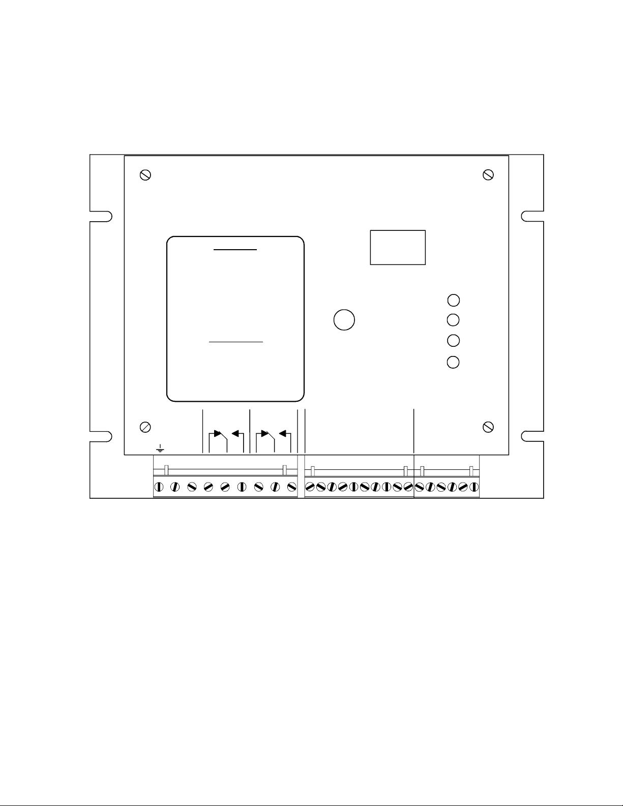
3. The shielded cables from the probes to the board should be run in conduit. The receiver
probe is connected to terminals labeled RCVR on the rightmost terminal block and the
transmitter probe to the terminals labeled TMTR on the same terminal block. Since the
probes are non-polarized, the order of lead connection is not important and since the probes
are identical, it does not matter which one is the transmitter and which one is the receiver.
Connect the shield leads (drain wires) from the probe cables to the terminals labeled SHLD.
4. The OVER and UNDER relays may be operated in a "follower" mode or a "memory" mode
depending upon the wiring of the RESET input. The operational modes and required
connections are described below.
a) For "follower" mode, jumper RESET and COM together on the center terminal block. In
this mode, when an OVER or UNDER condition occurs, the appropriate relay drops out,
and the OVER or UNDER LED comes on. After the fault condition is corrected, the relay
returns to the normally energized condition and the LED goes out. Automatic reset is
normally selected to control the operation when the fault condition is automatically
removed or the DS3410 is wired into the stop circuit of the machine.
b) For "latch" mode, wire the RESET and its associated COM terminal to the normally open
contacts of a switch, relay, or controller output. In this mode, when a fault condition
occurs, the relay drops out and the OVER or UNDER LED comes on. After the fault
condition is corrected, the contact must be momentarily closed to energize the relay.
5. Calibration Enable. Connect a N.O. push button across the terminals labeled CAL and
COM. Closing a contact across these terminals initiates a calibration cycle. If there is no
material between the probes when calibration is initiated, the DS3410 waits for material to
be presented and then after a time delay determined by the setting of switch 1, actual
calibration begins.
The calibration data is stored in the non-volatile memory as selected by the signals on SEL1
and SEL2 (and ENABLE if the ENABLE input is used for memory select per the switch 2
setting). Use of the CAL input is optional since the push button on the DS3410 front panel
performs the exact same function. This input simply allows the calibration function to be
initiated remotely.
6. Switches or contacts may be connected between SEL1 and COM and SEL2 and COM to
allow selection of four different calibration memories. Calibration data is stored in the
memory that is selected at the time calibration occurs. Switching between calibration
datasets can be done at any time during DS3410 operation.
DIP switch 2 allows the ENABLE input to be used as a third memory select input. When
switch 2 is ON, the ENABLE input acts an SEL3 input providing another four memories for
calibration for a total of eight. The memories are selected through the binary combination
of signals on the SEL and ENABLE inputs as follows:
Memory SEL1 SEL2 ENABLE Switch 2
1 off off off on or off
2 on off off on or off
3 off on off on or off
4 on on off on or off
5 off off on on
6 on off on on
7 off on on on
8 on on on on