
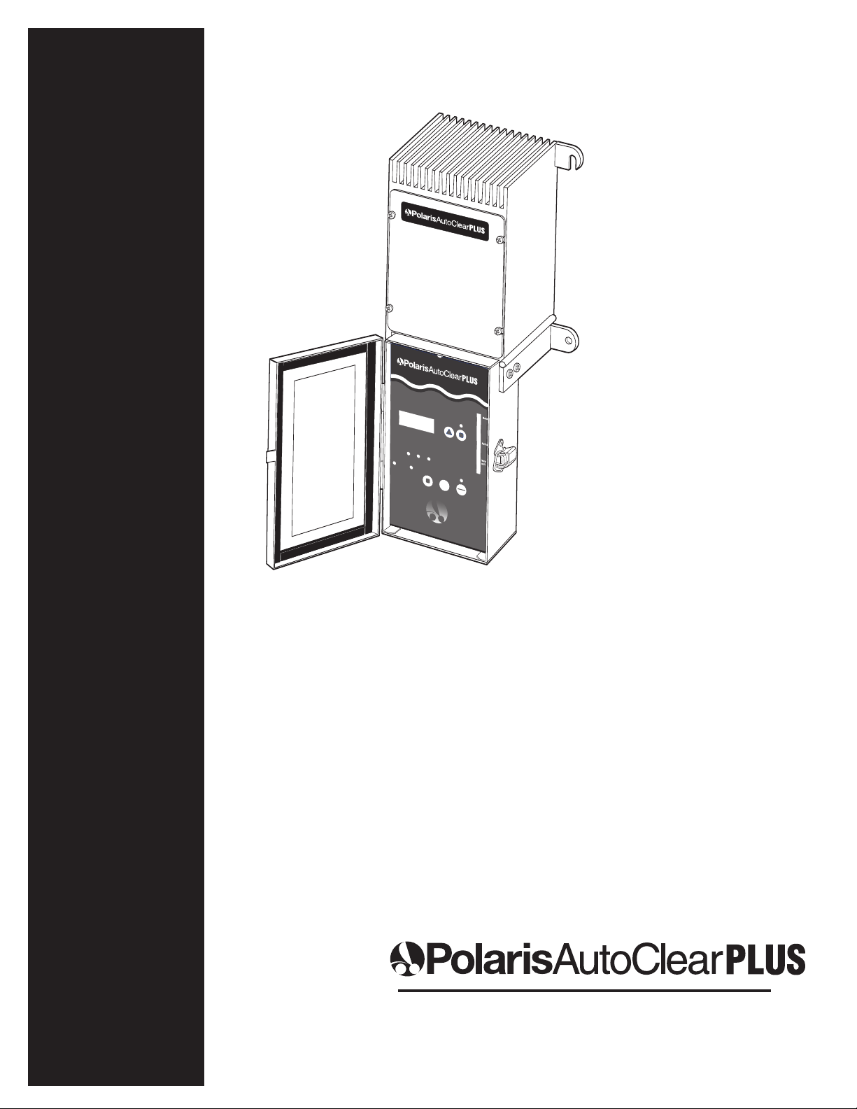
Polaris AutoClearPLUS Manuel du produit
IMPORTANT INFORMATION
INSTALLATION AND
MAINTENANCE GUIDE
SERIAL NUMBER
Normal
Add Salt
Very Low
Salt
PowerFlowService
Auto
Cycle Sanitizing
Restart
Cycle
24Hours
Boost
On
Off
On
Off
Tes t
Up Program
Program
PowerFlow Service
Auto
Cycle Sanitizing Restart
Cycle
24Hours
Boost
THE NATURALWAYTOSPARKLINGCLEARWATER
Up
TestOn
Off

www.polarispool.com
Important Information
•For your protection, read all instructions carefully before installing or operating this equipment.
• Do not allow children to handle this product.
•Installation of this equipment should be performed by a licensed electrician and conform to all
National Electric Code (NEC), state and local codes. Installations in Canada must comply to
CEC requirements.
•To avoid electrical shock:
Install all electrical equipment at least 10 feet (3 m) from inside wall of pool or spa.
Aground-fault circuit interrupter (GFCI) must be utilized with this device.
Do not bury cell cord but position it to eliminate contact with lawn mowers, hedge trimmers
and other such equipment.
• Damaged cell cords must be replaced by a Polaris Authorized Service Center.
For customer service or support:
•For on-line support: www.polarispool.com
•To contact Polaris:
US and Canada
Customer Service
2620 Commerce Way
Vista, CA 92081-8438
1-800-822-7933
Specifications
Input Power: 120 VAC 50/60 Hz, 3.0 Amps or 240 VAC 50/60 Hz, 1.5 Amps
Output Power: 26-28 VDC @ 5.2 Amps (max.)
Capacity: 40,000 Gallons
Operating Temp: 50° - 104° F, water temperature
Display LCD, LED array

www.polarispool.com
The Polaris AutoClearPLUS®automated pool chlorination system sanitizes pools and
spas naturally, providing clean, clear water with no harsh chemicals and no eye or
skin irritation.
Using an electrolytic cell installed on the pool return line, the AutoClearPLUS converts
salt (NaCL) dissolved in the pool water into pure chlorine. The chlorine is used to
sanitize the pool, then converts back to salt. This process is repeated indefinitely,
supplying all pool and spa chlorine needs.
Introduction
Normal
Add Salt
Very Low
Salt
PowerFlowService
Auto
Cycle Sanitizing
Restart
Cycle
24 Hours
Boost
On
Off
On
Off
Tes t
Up Program
1
2
5
3
4
Program
Power FlowService
Auto
Cycle SanitizingRestart
Cycle
24 Hours
Boost
THENATURALWAYTO SPARKLINGCLEARWATE R
Up
Tes tOn
Off
1. Power Supply
2. Controller
3. In-Line Cell with Integrated
Flow Switch
4. 2" Union Fitting (2)
5. 2x1-1/2" Reducer Bushing (2)
Polaris AutoClearPLUS Components
www.polarispool.com
Simple installation in four easy steps:
•Determine pool/spa capacity (total gallons) and prepare the pool water
• Install the cell
• Install the power supply and controller
• Start and set the system
Prepare the Pool Water
Figure the pool/spa capacity, total gallons being circulated by the primary pump, using the
guidelines specified below.
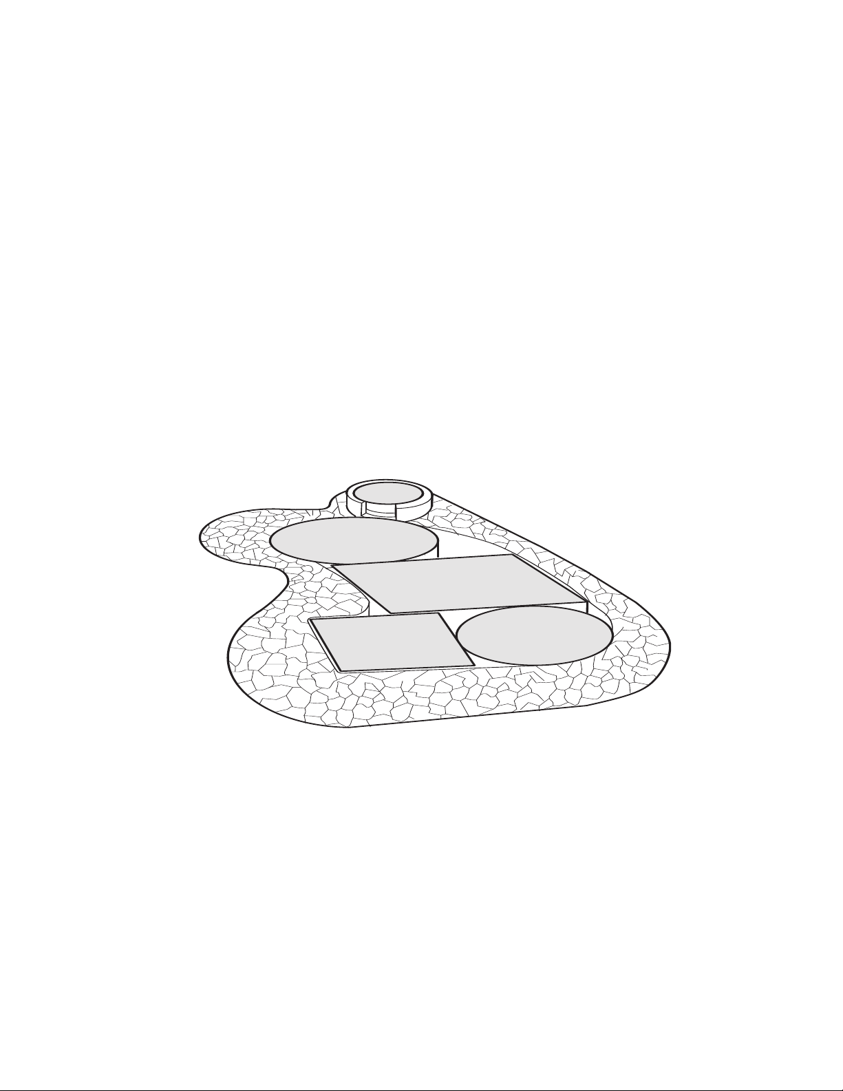
Rectangular Pools: Length x Width x Average Depth x 7.48
Round Pools: Radius x Radius x 3.14 x Average Depth x 7.48
Oval Pools: Maximum Length x Minimum Width x Average Depth x 5.7
Irregular Shaped Pools: Divide the overall shape into smaller forms and figure the
capacity in each. Then add all areas together to obtain total gallons.
Superchlorinate (shock) the pool to eliminate any chlorine demand. Then test and balance
the pool to the following specifications. For specific chemical requirements, refer to the Reference
section of this document. For vinyl or fiberglass pools, refer to manufacturer’s guidelines.
Free Chlorine 1.0 - 3.0 parts per million (ppm)
pH 7.4 - 7.6 ppm
Total Alkalinity 80 - 120 ppm
Calcium Hardness 200 - 400 ppm (Do not install system if
hardness is over 1200 ppm.)
Cyanuric Acid (Stabilizer) Per local requirements
Metals,Phosphates and Nitrate 0ppm
Installation Instructions
1

www.polarispool.com
Use a test strip (AquaChek or equivalent) to determine the salt content of the water. Add
enough salt to attain a level between 3000-3500 ppm, the optimum level is 3250 ppm. Use
only granulated, evaporated sodium chloride (99%plus pure) and never use salt with anti-
caking additives or Yellow Prussiate of Soda. Water conditioning pellets (with no additives)
can be used but may take longer to dissolve. When sodium bromide is used, it is in addition
to the required sodium chloride levels. Refer to the sodium bromide requirements chart in the
Reference section.
Per gallon salt requirements are approximately, 50 lbs. per 2000 gallons of water. Refer to the
chart below for exact dosages.
•To add salt to existing pools, pour salt around the perimeter and mix with a brush to
ensure quick and even distribution.
•For new or colored plaster, wait 10-14 days after pool is filled to allow adequate time
for the plaster to cure. Use only fine granulated salt. Pour salt evenly around the pool and
run pump continuously for three hours.
Pounds Of Salt Needed For 3250 ppm
Existing Salt Pool Volume in Gallons
Concentration 10,000 15,000 20,000 25,000 30,000 35,000 40,000
0 ppm 271 lbs. 407 lbs. 542 lbs. 678 lbs. 813 lbs. 949 lbs. 1084 lbs.
250 ppm 250 lbs. 375 lbs. 500 lbs. 626 lbs. 751 lbs. 876 lbs. 1001 lbs.
500 ppm 229 lbs. 344 lbs. 459 lbs. 573 lbs. 688 lbs. 803 lbs. 917 lbs.
750 ppm 209 lbs. 313 lbs. 417 lbs. 521 lbs. 626 lbs. 720 lbs. 834 lbs.
1000 ppm 188 lbs. 281 lbs. 375 lbs. 469 lbs. 563 lbs. 657 lbs. 751lbs.
1250 ppm 167 lbs. 250 lbs. 334 lbs. 417 lbs. 500 lbs. 584 lbs. 667 lbs.
1500 pm 146 lbs. 219 lbs. 292 lbs. 365 lbs. 438 lbs. 511 lbs. 584 lbs.
1750 ppm 125 lbs. 188 lbs. 250 lbs. 313 lbs. 375 lbs. 438 lbs. 500 lbs.
2000 ppm 104 lbs. 156 lbs. 209 lbs. 261 lbs. 313 lbs. 365 lbs. 417 lbs.
2250 ppm 83 lbs.125 lbs. 167 lbs. 209 lbs. 250 lbs. 292 lbs. 334 lbs.
2500 ppm 63 lbs.94 lbs. 125 lbs. 156 lbs. 188 lbs. 219 lbs. 250 lbs.
2750 ppm 42 lbs. 63 lbs. 83 lbs. 104 lbs. 125 lbs. 146 lbs. 167 lbs.
3000 ppm 21 lbs. 31 lbs. 42 lbs. 52 lbs. 63 lbs. 73 lbs. 83 lbs.
3250 ppm 0 lbs. 0 lbs. 0 lbs. 0 lbs. 0 lbs. 0 lbs. 0 lbs.
Install the Cell
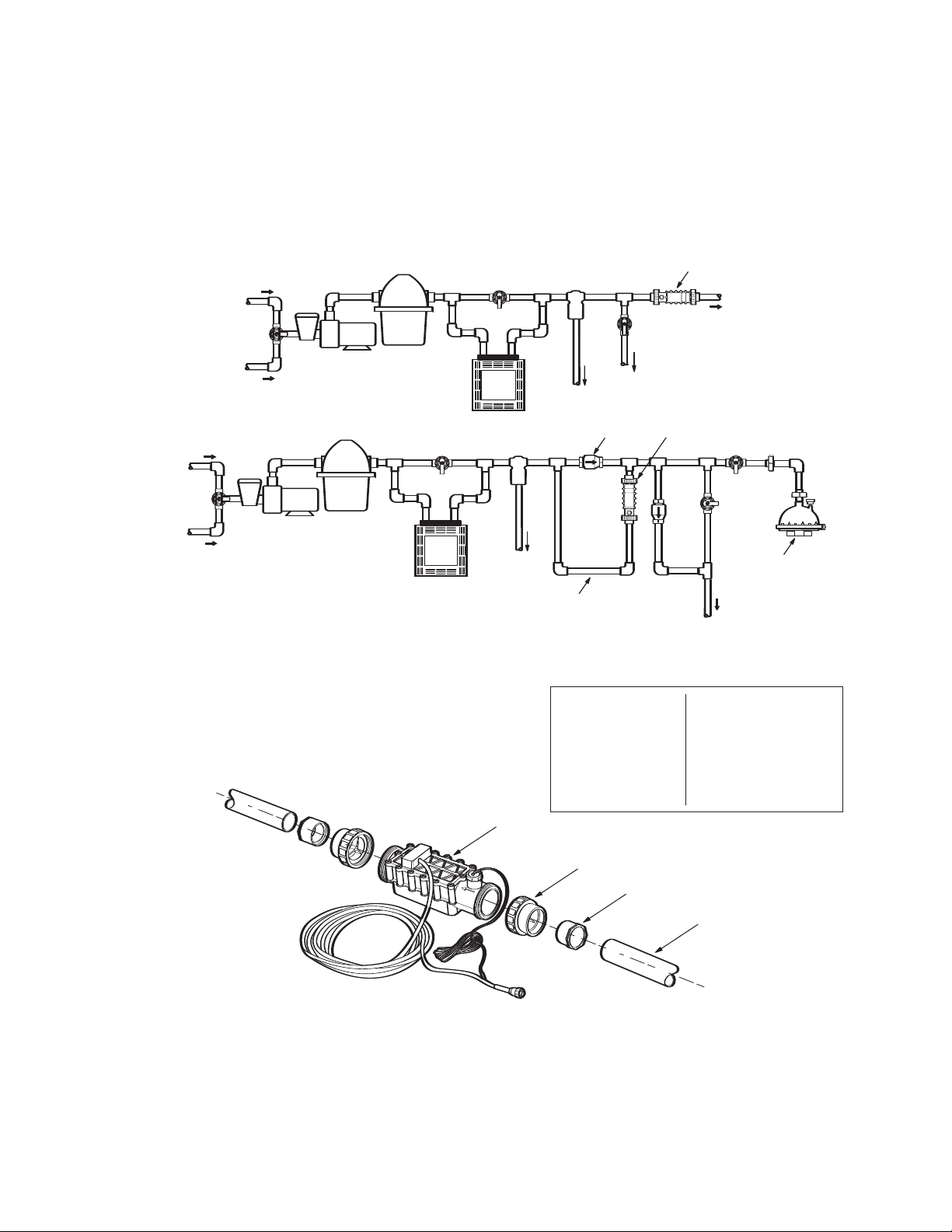
Install the cell in a section of straight pipe, at least 22 inches long, downstream from all pool
equipment. Position the cell within 10-12 feet of the controller/power supply location to
accommodate the 12 ft. cell cord. If an in-floor cleaning system or other high-flow application
is present, install the cell on a bypass manifold and include a check valve.
The cell can be positioned vertically or horizontally.
1. Turn off pool pump.
2. Measure and cut the pipe based on the
piping configuration. Leave at least 6 inches
of straight pipe in front of the cell.
3. Clean all surfaces and apply primer to cut pipe.
4. Glue union fittings (and reducer bushings if using 1-1/2" pipe) into pipe.
5. Install cell and hand tighten unions.
6. Verify that cell wire and flow switch wire are secure.
www.polarispool.com
2
Filter
Pump
Heater
To
Spa
To Pool
Cleaner
Filter
Pump
Heater
To
Spa
Bypass
Manifold
In-Floor
Cleaning
System
Cell
Check
Valve
Cell
From
Pool
From
Spa
From
Pool
From
Spa
To Pool
To
Pool
Cell
Union Fitting
Reducer (if required)
Pipe
2" Pipe 1-1/2" Pipe
Length of cell Length of cell, union
and union fittings fittings and reducer
bushings
Approx. 11-3/4" Approx. 12"
Install Power Supply and Controller
Power Supply
Install the power supply within 10 - 12 feet of the cell to accommodate the 12 ft. cell cord.
Mount it slightly above eye level on a wall, protected from direct sunlight, rain and flooding.
Leave at least 10 inches of clearance below and to the sides of the supply for the controller.
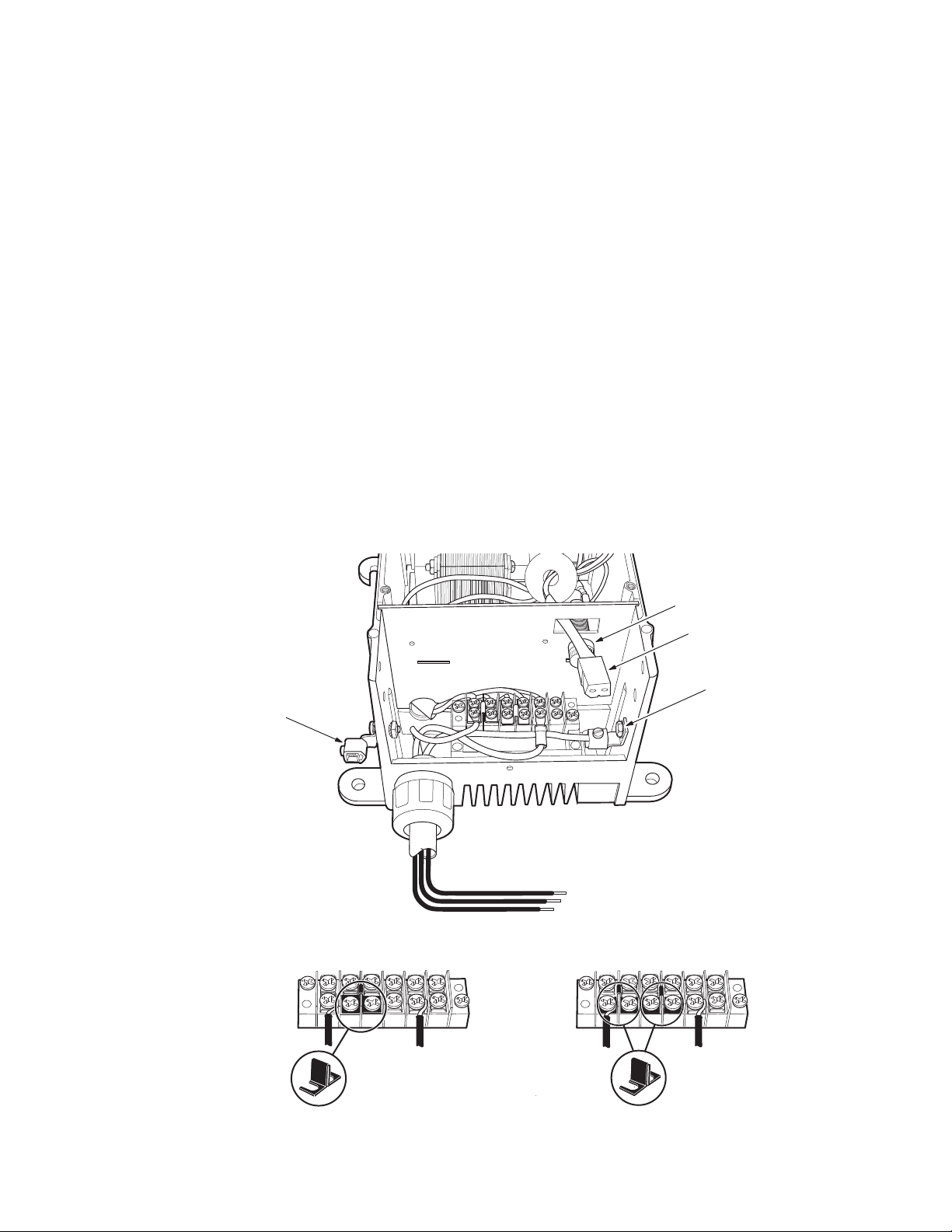
Connect AC power:
• Use 18AWG wire (min.) and 12AWG ground wire (in non-metallic conduit) to wire the AC
power to the load side of the time clock or pump.
• If installing with a Polaris Eos or Jandy AquaLink control system, wire unit to its own,
independent power source, not the load side of the filter pump relay.
• Use a copper bonding wire (8AWG min.) to ground the controller to the common bonding
grid for the pool equipment.
• Attach load and grounding wires for 240VAC or 120VAC. Unit is shipped 240VAC from
factory. To convert to 120VAC, replace the 1.5 Amp fuse installed with the 3 Amp fuse
included in parts bag next to wiring block.
www.polarispool.com
3
220 VAC
Connection
123456
110 VAC
Connection
123456
AC Input
Ground
Load 1
Load 2
Jumper Jumper
Bonding Lug
Grounding Lug
Controller Connection
Fuse
Power Supply with
Face Plate and Connection Cover Plate Removed
123456
220 VAC Connection
123456
Jumper Jumpers
LL2 LN
110 VAC Connection
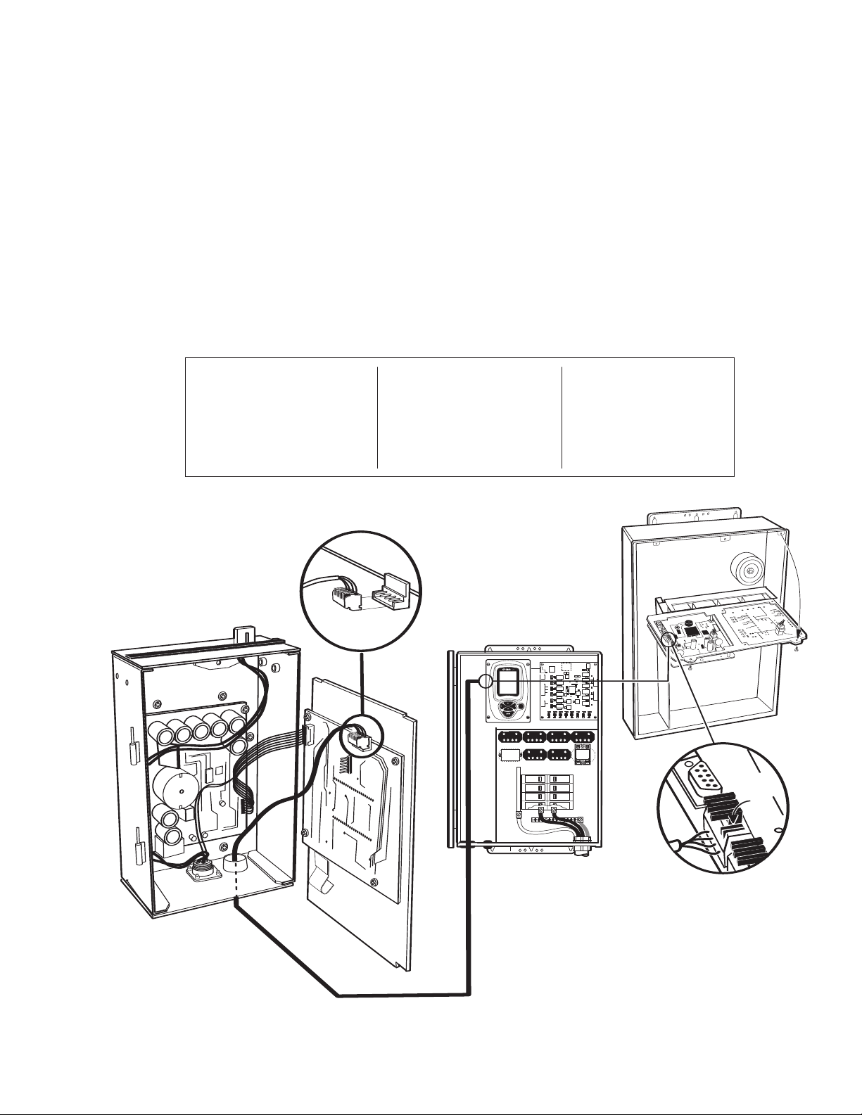
AC Wiring
Controller
The AutoClearPLUS can be operated as a stand alone unit or can be connected to the
Polaris Eos or Jandy AquaLink automation control system. These multi-functional systems
are designed to fully control the chlorinator.
To connect unit to an automated control system:
1. Remove the face plate from the chlorinator controller unit.
2. Slide 4-wire connector cable (sold separately) through grommet in base of controller and
connect (as diagrammed) to block on back of controller face plate.
3. Verify that all other connections are secure, then reattach the face plate.
4. At the control system equipment, attach the chlorinator wire to the 4-pin connector
on the Eos command center board (or to the red connector inside the Jandy power
center) using the following wire color/pin sequence.
At Chlorinator At Eos At Jandy
Wire Color/ Pin# Wire Color/ Pin # Wire Color/Pin #
Red / 1 Black / 1 Red / 1
Black / 2 Yellow / 2 Black / 2
Yellow / 3 Green / 3 Yellow / 3
Green / 4 Red / 4 Green / 4
www.polarispool.com
Eos Command Center
Eos Command Center
Board Connection
Lock
Down
on
Wire
E
SVC
High Power Relay 1 High Power Relay2 High Power Relay3 High Power Relay 4
Optional
High Power
Relay 6
GND
SNSR1
GND
SNSR2
GND
SNSR3
GND
SNSR4
GND
SNSR5
+
24VDC
GND
PRE
OUT
Optional
High Power
Relay 7
Optional
High Power Relay5
Or 2 Speed
Pump Relay
Optional
High Power
Relay 8
Or 2 Speed
Pump Relay
HP1 HP2 HP3 HP4 HP5 HP6 HP7 HP8
LP1 LP2 LP3LP4 LP5 LP6
VLV6 VLV5 VLV4 VLV3 VLV2 VLV1
AutoClearPLUS
Controller
AutoClearPLUS
Wire Connection
www.polarispool.com
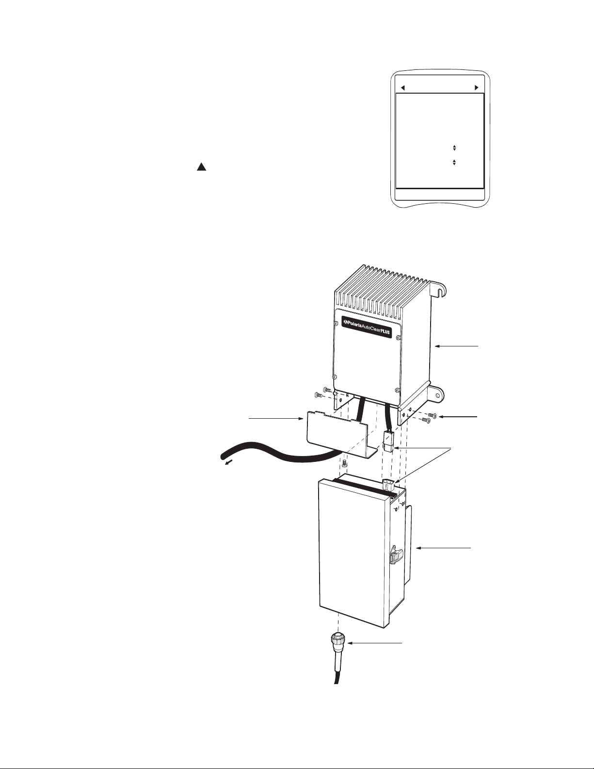
All adjustments to output and superchlorination
functions are made through the Eos system via the
Salt Chlorinator control screen.
Salt reading displays (Test button) and temperature
adjustments (Program button) can still be
accomplished at the AutoClearPLUS unit.
When the Eos (or another controller) is connected, a
flashing triangle will appear in the top left hand
corner of the AutoClearPLUS LCD screen.
Install controller:
1 Replace and secure power supply face plate
and connection cover plate.
2. Remove side anchor screws (4).
3. Engage controller connector.
4. Position controller under power supply.
Align anchor screw holes with holes on
power supply. Insert and tighten
anchor screws.
5. Insert cell wire plug into controller
receptacle. Push upwards and turn
clockwise to engage. Tighten securely.
Cover Plate
Power Supply
Anchor Screws
Controller Connection
Controller
Cell Wire Plug
To Electrical
Power Supply
Wed, Aug 29 2:04pm
AutoClear
2600
ppm
Mode Normal
Chlorination Off
Air 60° Pool 60° Spa 60°
Eos Control Screen
www.polarispool.com
4Start and Set the System
Wait 24 hours from last pool water adjustments to make certain that the salt is completely
dissolved and all chemicals have been thoroughly circulated.
1. Turn on pool pump.
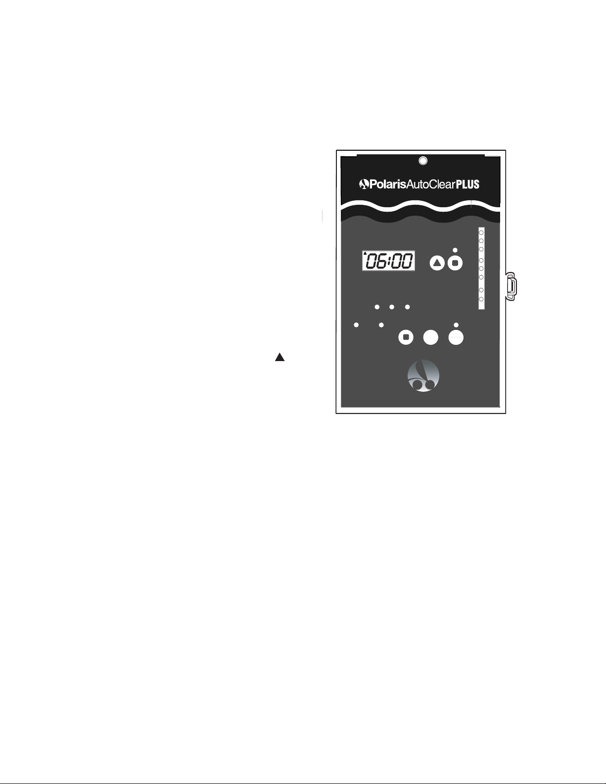
2. After a 5 second delay, the display
will illuminate.
Power (green) - power is on to unit.
Flow (green) - system has sufficient
water flow to operate.
AutoCycle (green) - system is running
on preprogrammed run cycle.
Sanitizing (green) - cell is producing
chlorine.
The Service light (red) lights only
if a problem condition (i.e. low flow)
is present.
The large LCD display shows the
factory-set system run time. If an
automation system is controlling the
chlorinator, a flashing triangle is
displayed in the upper left corner.
Within one minute the LED bar graph
will indicate current salt levels in the
pool. All lights (green, yellow and red)
should illuminate. If only yellow and
red lights are lit, press the Test button
to determine the salt concentration
and adjust as necessary to attain
3000-3500 ppm (optimum level is
3250 ppm).
3. To adjust the run time, press the Up button to set minutes and hours. If the run time is
changed, the new run time will be active for the next run cycle.
To reset the run time, press the Restart Cycle button. The readout will display the full run
time and the cycle clock will start a new countdown.
4. The AutoClearPLUS includes a water temperature feature.
To set, press and hold the Program button. The display will flash a pre-set temperature
reading in degrees fahrenheit. Use the Up button to adjust temperature. Adjustments are
made in increments of five degrees in a range from 55-100° F. When the adjustment is
complete, the display will revert back to the run time setting.
5. The pool pump must be set to run longer than the AutoClearPLUS unit. A minimum
of five hours per day is required for proper circulation and filtration.
Up Program
Normal
Add Salt
Very Low
Salt
Power Flow Service
Auto
Cycle Sanitizing Restart
Cycle
24 Hours
Boost
THE NATURAL WAY TO SPARKLING CLEAR WATER
Test On
Off
Table des matières
Autres manuels Polaris Filtre de piscine


Manuels Filtre de piscine populaires d'autres marques


Davey
Davey EcoPure DEP2140 Manuel utilisateur

JUWEL Aquarium
JUWEL Aquarium EccoSkim Manuel utilisateur

POLYGROUP LIMITED
POLYGROUP LIMITED SFS600 Filter System with F600C Pump Manuel utilisateur

Pentair Pool Products
Pentair Pool Products Filter CFW Series Manuel utilisateur

Oase
Oase Skimmer 250 Manuel utilisateur

Oase
Oase CrystalSkim 350 Manuel utilisateur