PlayActive MINI Beachcomber Fiche technique

MINI Beachcomber
Children Electric
RIDE ON
Owner’s Manual
with Assembly Instructions
Styles and colours may vary.
Made in China.
The owner’s manual contains important safety information as well as assembly, use and
maintenance instructions.
The Ride-on Car must be assembled by an adult who has read and understands the
instructions in this manual.
Keep the package away from children and dispose of properly before use.
Keep this manual for future reference.
With remote control function

On the purchase of your new Ride-On.
This ride-on car will provide your child with many miles of riding of
enjoyment. To help assure you and your rider a safe ride we ask you to
please read this manual carefully, and keep it for future reference.
Follow the recommendations in this manual, they are designed to improve
the safety and operation of your ride-on car and it’s rider.
Battery
Fuse
Charger
6V7Ah*2 or 6V10Ah*2 or 12V10Ah*1
10A & 20A
12V1000mA
Suitable age:
Load Capacity:
Speed:
Size of car:
Power way:
Charge time:
37~96 Months
Under 40 kgs
3~5km/h
138*80*61 CM
Charging type
8 ~ 12 hours
About Your New Ride-On │1
VER: SMS-JJ299-EN-151229
MINI Beachcomber Children Electric Ride On manufactured by Zhejiang
Jiajia Ride-On Co., Ltd.
(Add: Xincang Industrial Zone, Pinghu City, Zhejiang Province,
P.R.China). The MINI logo and the MINI word mark are trademarks of
BMW AG and are used under license.
VER: SMS-JJ299-EN-RC-151229

2
4
2
3
2
16
A
B
C
D
E
F
1
2
3
4
5
6
7
8
9
10
11
12
13
14
15
16
17
18
19
2
2
8
2
2
1
4
1
1
1
1
1
1
1
1
1
1
2
1
3
20
1
1
1
G
H
i
1
1
1
PART
NO.
REMARKS
PART NAME
Q’ty (pcs)
Gear box
Driving wheel
Ø12 washer
Motorhood
Front wheel
Charger
Ø10 locknut
Tool box
Vehicle body
Steering column
Front axle
Rear axle
Seat
Steering wheel
M5x35 machines screw
Ø5 nut
Windshield
Rear window
Sport bar
M5x16 machine screw
Hubcap
Split pin
Ø10 washer
Spanner
Ø4x12 screw
Placed on the steering wheel
Placed on the steering wheel
Assembled by factory
One pair
1pc labeled “L”, and 1pc labeld “R”
1 pcs for spare
1 pcs for spare
Parts List │2
Assembly package
Remote controller
R/C driver
Ø5 nut
M5x12 machine screw

1
2
33
4
5
7
B
9
10
11
G
H
13
17
8
18
15
16
F
F
12
14
18
19 A
CD
6
E
F
i
20
NOTE: Some parts shown are assembled on both sides of vehicle
Parts Diagram │3

●Non-rechargeable batteries are not to be recharged.
●If removable rechargeable batteries are used, the are only to be charged under adult
supervision.
●Remove rechargeable batteries from the product before charging.
●Do not mix old and new batteries. Do not mix different types of batteries: alkaline, standard
(carbon-zinc) or rechargeable (nickel-cadmium).
●Insert batteries as indicated inside the battery compartment, anode to andoe, cathode to
cathode.
●Remove batteries during long periods of non-use. Always remove exhausted batteries from the
product. Battery leakage and corrosion can damage this product. Dispose of batteries safely.
●Never short circuit the battery terminals.
BATTERY INFORMATION
Before You Begin Assembly │4
FOR THE SAFETY OF YOUR CHILD, PLEASE READ ALL WARNINGS AND
ASSEMBLY/USE INSTRUCTIONS. KEEP THIS GUIDE FOR FUTURE REFERENCE.
• ADULT ASSEMBLY REQUIRED. The product contains small parts, which are for
adult assembly only. Keep children away when assembling.
• Always remove protective material and poly bags and dispose before assembly.
• Make sure that the power switch is turned “OFF” before assembling the ride-
on.
• Before first time use, charge the battery for at least 4 to 6 hours.
• Assembly tools required:
WARNING!
Screwdriver
(not included)
Long nose pliers
(not included)
Spanner

1. Turn over the vehicle body and cut off the plastic tie on the frotn wheel axle with
scissors.
2. Remove the M5x16 screw, washer and nut from the front wheel axle.
3. Adjust the wheel axle so that the axle is in the correct positon as shown in
picture at right; then reinsert the M5x16 screw and washer as shown, making
sure the M5x16 screw goes through the holes in the metal plates A and B
(ensure plate B sits over plate A as shown with stopper, to prevent fingers
becoming trapped while steering), attach the locknut and tighten securely.
Attach the Front Axle │5
A
B
Stopper
M5x16 screw
Ø5 locknut

1
Remove all the parts from the rear axle.
1. Insert the rear alxe into the hole in the vehicle body.
Attach the Rear Axle │6

1
2
3
4
9
5
67
8
9
x2
1. Slide the gear box onto the rear axle (Left Side). “R” labeled gear box should be fit to
the “R” side of vehicle body; “L” labeled gear box should be fit to “L” side of vehicle body.
2. Slide the driving wheel onto the rear axle. And keep the driving wheel match with the
gear box.
3. Slide the Ø10 Washer onto the rear axle.
4. Tight a Ø10 Locknut to the end of the rear axle with a spanner.
5. Slide the gear box onto the rear axle (Right Side).
“R” labeled gear box should be fit to the “R” side of vehicle body; “L” labeled
gear box should be fit to “L” side of vehicle body.
6. Slide the driving wheel onto the rear axle. And keep the driving wheel match with the gear box.
7. Slide the Ø10 Washer onto the rear axle.
8. Tight a Ø10 Locknut to the end of the rear axle with a spanner. HINT: An extra spanner has
been provided to hold the Ø10 locknut on the other side of the rear alxe while tightening the
locknut on the other side.
9. Fit the hubcap to the wheel cover.
Attach the Rear Wheels │7
Rear axle
Driving wheels are more bigger than front wheels
Tools required: Spanner

1
2
3
4
5
Front axle
Tools required: Spanner
Remove all the parts from the front axle.
1. Slide a Ø10 washer onto the front axle.
2. Slide the normal wheel onto the rear axle.
3. Slide a Ø10 washer onto the front axle.
4. Tight a Ø10 Locknut to the end of the front axle with a spanner.
5. “Snap” the hubcap to the wheel cover.
Repeat this step for the other side.
GAP
After assembling any wheel to the axles, please check the gap
between the screw thread and the collapsible (refer to below picture), if
the gap is too big, please add two or three washers inside the wheel, But
after tightening the nut outside the wheel, please turn the wheel by your
finger to check if the wheel can run smoothly, this is very important,
because if the wheel can run smoothly, it is ok, but if the nut press the
wheel and the wheel can’t run smoothly, the motor will be broken easily!
Then you need to decrease one or two washers to make sure the wheel
can run smoothly!
Attach the Front Wheels │8
4
5
1
32
1
2
23
3
1
5
4
6
2
2
2
2
2
2
2
2
2
2
2
2
2
2
2
2
2
2
2
2
2
2
2
2
2
2
2
2
2
2
2
2
2
2
2
2
2
2
2
2
2
2
2
2
2
2
2
2
2
2
2
2
2
2
2
2
2
2
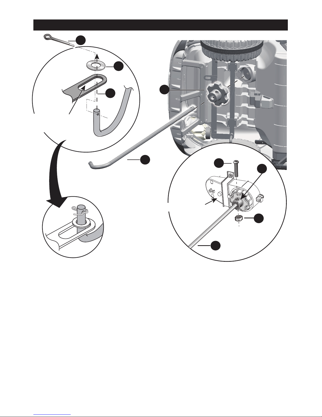
Hole in the
front axle linkage
Turn the vehicle body on its side.
1. Slide a Ø10 washer onto the steering column from the straight end.
2. Insert the straight end of steering column up through the hole at the front of
vehicle body from bottom side, and out through the hole in the dash.
3. Insert the bent end of steering column through the hole in the front axle
linkage.
4. Fit a Ø10 washer onto the steering column.
5. Insert a split pin into the hole in the steering column, bend the ends of split pin
back using a long nose pliers.
Attach the Steering Column │9
Turn the vehicle body on its side. Remove the M5x22 machine screw and Ø5
nut from the R/C driver with a screwdriver.
1. Attach the R/C driver to the steering gear box, and make it match with
steering gear box.
2. Insert the straight end of steering column up through the hole in the R/C
diver, the hole in the steering gear box from the bottom side, and out
through the hole in the dash.
3. Line up the holes in the R/C driver and the hole in the steering column,
tighten a M5x22 machine screw and Ø5 nut back in the same location with a
screwdriver.
4. Insert the bent end of steering column through the hole in the front axle
linkage.
5. Fit a Ø10 washer to the steering column.
6. Insert a split pin into the hole in the steering column, bend the ends of split pin
back using a long nose pliers.
Steering Gear Box
Ce manuel convient aux modèles suivants
1
Table des matières


