PKP FOS01 Manuel utilisateur

PKP Prozessmesstechnik GmbH
Borsigstraße 24
D-65205 Wiesbaden- ordenstadt
Tel.: ++49-(0)6122-7055-0
Fax: ++49-(0)6122-7055-50
Email: [email protected]
Instruction Manual
FOS01
Optoelectronic Levelswitch

G
1. General information 4
2. Safety 5
3. Specifications 9
4. Design and function 10
5. Transport, pac aging and storage 11
6. Commissioning, operation 12
7. Maintenance and cleaning 13
8. Faults 14
9. Warranty 15
10. Dismounting, return and disposal 15
Table of Contents

1. General information
■ The mini limit switch described in the operating instructions has been manufactured
using state-of-the-art technology.
All components are subject to stringent quality and environmental criteria during
production. Our management systems are certified to I O 9001.
■ These operating instructions contain important information on handling the mini limit
switch. Working safely requires that all safety instructions and work instructions are
observed.
■ Observe the relevant local accident prevention regulations and general safety
regulations for the mini limit switch's range of use.
■ The operating instructions are part of the instrument and must be kept in the immediate
vicinity of the mini limit switch and readily accessible to skilled personnel at any time.
■ killed personnel must have carefully read and understood the operating instructions,
prior to beginning any work.
■ The manufacturer's liability is void in the case of any damage caused by using the
product contrary to its intended use, non-compliance with these operating instructions,
assignment of insufficiently qualified skilled personnel or unauthorised modifications to
the mini limit switch.
■ The general terms and conditions contained in the sales documentation, shall apply.
■ ubject to technical modifications.
■ Further information:
- Internet address: www.pkp.de
- Application concultant: Tel.: (+49) 6122 – 70 55 0
Fax: (+49) 6122 – 70 55 50
E-Mail: [email protected]
Explanation of symbols
WARNING!
... indicates a potentially dangerous situation, which can result in serious
injury or death, if not avoided.
CAUTION!
... indicates a potentially dangerous situation, which can result in light injuries
or damage to equipment or the environment, if not avoided.

Information
... points out useful tips, recommendations and information for efficient and
trouble-free operation.
DANGER!
...identifies hazards caused by electric power. hould the safety instructions
not be observed, there is a risk of serious or fatal injury.
WARNING!
... indicates a potentially dangerous situation that can result in burns, caused
by hot surfaces or liquids, if not avoided.
2. Saf ty
WARNING!
Before installation, commissioning and operation, ensure that the appropriate
instrument has been selected in terms of measuring range, design and
specific measuring conditions.
Non-observance can result in serious injury and/or damage to equipment.
Further important safety instructions can be found in the individual chapters of
these operating instructions.
2.1 Int nd d us
This instrument is designed to detect limit levels of liquids. The values given in chapter
"3. pecifications" must not be exceeded. The mini limit switch is not suitable for milky,
turbid, outgassing, sticky and crystallising media.
The mini limit switch has been designed and built solely for the intended use described
here, and may only be used accordingly.
The technical specifications contained in these operating instructions must be observed.
Improper handling or operation of the mini limit switch outside of its technical specifications
requires the instrument to be shut down immediately.
The manufacturer shall not be liable for claims of any type based on operation contrary to
the intended use.
2.2 P rsonn l qualification
WARNING!
Risk of injury should qualification b insuffici nt!
Improper handling can result in considerable injury and damage to equipment.
■ The activities described in these operating instructions may only be carried
out by skilled personnel who have the qualifications described below.
■ Keep unqualified personnel away from hazardous areas.
Skill d p rsonn l
killed personnel are understood to be personnel who, based on their technical training,
knowledge of measurement and control technology and on their experience and
knowledge of country-specific regulations, current standards and directives, are capable of
carrying out the work described and independently recognising potential hazards.
pecial operating conditions require further appropriate knowledge, e.g. of aggressive
media.
2.3 Sp cial hazards
WARNING!
For hazardous media such as oxygen, acetylene, flammable or toxic gases or
liquids, and refrigeration plants, compressors, etc., in addition to all stand-
ard regulations, the appropriate existing codes or regulations must also be
followed.
WARNING!
To ensure safe working on the instrument, the operating company must
ensure
■ that suitable first-aid equipment is available and aid is provided whenever
required.
■ that the operating personnel are regularly instructed in all topics regarding
work safety, first aid and environmental protection and knows the operating
instructions and, in particular, the safety instructions contained therein.

DANGER!
Danger of death caused by electric current
Upon contact with live parts, there is a direct danger of death.
■ Electrical instruments may only be installed and mounted by skilled
electrical personnel.
■ Operation using a defective power supply unit (e.g. short circuit from the
mains voltage to the output voltage) may result in life-threatening voltages
on the instrument!
WARNING!
Residual media in dismounted instruments may result in a risk to people, the
environment and the system. Take sufficient precautionary measures.
Do not use this instrument in safety or Emergency top devices. Incorrect use
of the instrument can result in injury.
hould a failure occur, aggressive media with extremely high temperature and
under high pressure or vacuum may be present at the instrument.
CE, Communauté Europé nn
Instruments bearing this mark comply with the relevant European directives.

3. Specifications
General Data
M asuring accuracy ±0.5 mm
Ambi nt light max. 10,000 Lux (immersed)
Mounting position any
W ight 0.15 kg
Design Data
M dium t mp ratur -30 ... +140 °C
Ambi nt t mp ratur -25 ... +70 °C
Working pr ssur 0 ... 5 MPa (0 ... 50 bar)
M asuring l ngth see drawing on page 9
Proc ss conn ction G ½ A, M16 x 1.5, ½ NPT etc. see drawings
Mat rials
■ ensor
■ Tip
■ Electronics housing
tainless steel 1.4571
Quartz
tainless steel 1.4301
Electrical Data
Supply voltag DC 24 V -25 ... +30 %
Supply curr nt max. 40 mA
Pow r consumption 1 W
Output
■ Voltage
■ Current
■ other
DC 24 V
0.5 A at Tu 70 °C
short-circuit protection, reverse voltage protection,
current, voltage and power limitation
Switching curr nt
(Tu = 70 °C)
0.5 A
El ctrical conn ction ■ PVC cable 3 x 0.14 mm²
■ Plug 4-pole series 713, M12
Ingr ss prot ction
■ With plug
■ With cable
IP 65 per EN 60 529
IP 66 per EN 60 529

Proc ss conn ction
Ø A
Spann r width
B
S aling fac
Ø C
M16 x 1.5 W24 Ø 21
G ½ A W30 Ø 26
½ NPT W24 -
4. Design and function
4.1 Description
This instrument is designed to detect limit levels of
liquids. For this purpose the sensor is equipped with a
V-shaped glass-tip. The model is also ideally suited for
level control, particularly in applications requiring high
precision. The measurement principle is independent of
the colour, refractive index, density, conductance and
dielectric constant of the liquid.
Integrated electronics include limit sensing and self-
calibration. The output is an open-collector pnp-transistor.
4.2 Instrum nt d sign
The sensor is a one-piece device consisting of a mechanical connection which depends
on the type of sensor, and integrated electronics built into a stainless steel housing. The
measuring length, ML, to the sealing face is always 24 mm.
Dim nsions in mm
Principle of operation
Gas
Liquid
Plug conn ction
cable
length
3000
green
LED
Mod l with cabl conn ction
4.3 Scop of d liv ry
Cross-check scope of delivery with delivery note.
S l ctabl proc ss conn ctions

5. Transport, packaging and storage
5.1 Transport
Check instrument for any damage that may have been caused by transport.
Obvious damage must be reported immediately.
5.2 Packaging
Do not remove packaging until just before mounting.
Keep the packaging as it will provide optimum protection during transport (e.g. change in
installation site, sending for repair).
5.3 Storag
P rmissibl conditions at th plac of storag :
■ torage temperature: -25 ... +70 °C
■ Humidity: 35 ... 85 % relative humidity (no condensation)
Avoidanc of xposur to th following factors:
■ Proximity to hot objects
■ Mechanical vibration, mechanical shock (putting it down hard)
■ oot, vapour, dust and corrosive gases
■ Potentially explosive environments, flammable atmospheres
tore the instrument in its original packaging in a location that fulfills the conditions listed
above. If the original packaging is not available, package and store the instrument as
described below:
1. Wrap the instrument in an antistatic plastic film.
2. Place the instrument, along with shock-absorbent material, in the packaging.
3. If stored for a prolonged period of time (more than 30 days), place a bag, containing a
desiccant, inside the packaging.
WARNING!
Before storing the instrument (following operation), remove any residual
media. This is of particular importance if the medium is hazardous to health,
e.g. caustic, toxic, carcinogenic, radioactive, etc.
6. ommissioning, operation
When unpacking the mini limit switch check all items for external damage. A functional
test may be carried out prior to the installation. To do this, the device should be temporarily
connected and the sensor-tip immersed in and then withdrawn from a glass of water.
WARNING!
The electrical connection must only be carried out by qualified skilled
personnel. Observe the relevant VDE regulations.
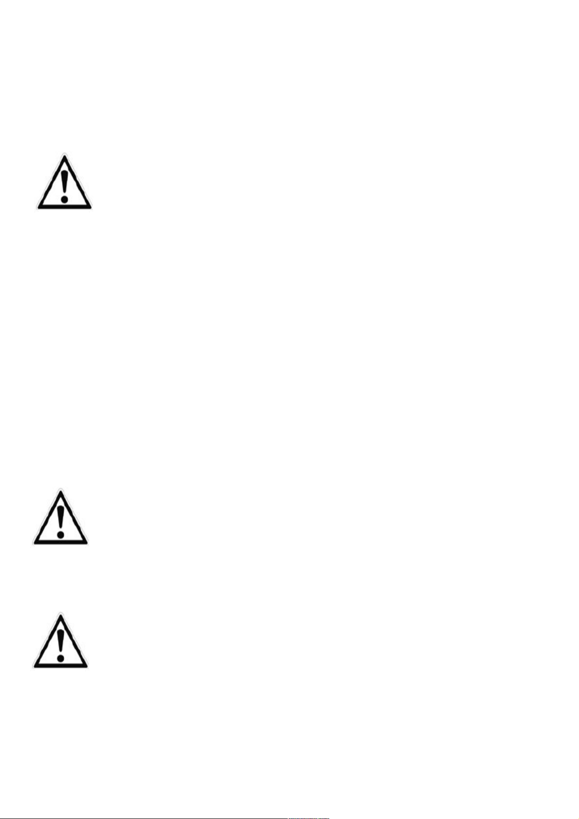
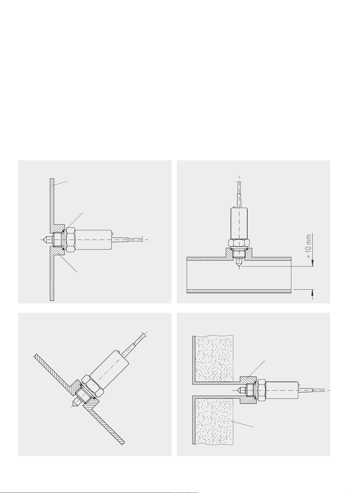
6.1. Installation instructions
tank or pipe wall
rubber or metal seal
welded adapter
ATTENTION!
In the case of
electropolished pipes
min. distance can be
much larger than 10 mm.
long adapter
Insulation
horizontal installation v rtical installation
inclin d installation high-t mp ratur m dium
Table des matières
Autres manuels PKP Changer


