PermaGreen Supreme ULTRA SE A1A Mode d'emploi

Repair Manual
Ride-On Ultra SE Spreader Sprayer
MODEL
Model# ULTRA SE A1A
Serial #__________________
FOR TECHINCAL SUPPORT
For additional instructions please call 800.346.2001, or your local distributor (below)
Direct all inquiries to:
DOCUMENT ID: U005M
Perma Green Supreme, Inc.
5609 Murvihill Rd
Valparaiso, IN 46383-8324
© 2004 Perma Green Supreme, Inc. U.S. Patent # 6,336,600 & Patents Pending. Ride-On is a registered trademark of Perma Green Supreme, Inc. All Rights Reserved.

TABLE OF CONTENTS
This manual contains information on repair of the Ride-On® Ultra Spreader Sprayer safely. For technical support,
parts orders, or warranty inquires, please call Perma Green Supreme, Inc. at 800.346.2001 or your local distributor
(on page 1).
All information in this publication is based on the latest product information available at the time of printing. Perma
Green Supreme, Inc. reserves the right to make changes without notice and without obligation.
This manual should be considered a permanent part of the machine. Record the serial number for ordering parts and
when making technical or warranty inquiries.
INTRODUCTION
page2
© 2004 Perma Green Supreme, Inc. All rights reserved.
DOCUMENT ID: U005M
Pressure Unloader Valve (clean)..................................... 3
Pump (replace)................................................................ 3
Spray Tank (replace)....................................................... 4
Nozzles (clean/replace).................................................. 4
SPRAY SYSTEM
Hopper (replace)............................................................. 5
Deector Lever & Cable (replace).................................... 5
Hopper Shut-Off Plate (replace)...................................... 6
SPREAD SYSTEM
DRIVE-TRAIN RELATED
Engine Removal & Installation......................................... 7
Engine Oil (change)......................................................... 8
Drive Belt (replace).......................................................... 8
Clutch Removal & New Installation.................................. 9
Clutch Arm (replace)........................................................ 10
Idler Pulley (replace)....................................................... 10
Shift Rod Ends (replace).................................................. 11
Transaxle (replace).......................................................... 11
Articulating Joints (replace)............................................ 12
Roller Bearings (replace)................................................. 12
Brake Adjustment............................................................ 13
Battery (change out)....................................................... 13
Grease Machine................................................................ 14
Winterize Machine............................................................ 14
GENERAL MAINTENANCE

© 2004 Perma Green Supreme, Inc. All rights reserved.
DOCUMENT ID: U005M
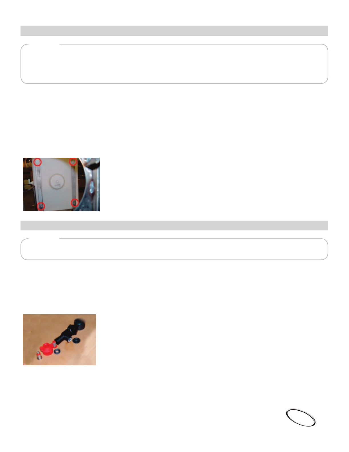
Replace Pump
1 Loosen hose clamps and disconnect hoses from pump
2 Unplug electrical connector from pump
3 Unscrew the (4) 10-24 nuts from the pump using 3/8” nut driver
4 Remove pump
5 Remove pump wiring harness including pump switch and replace with new harness
6 Put on new pump assembly on leg bolts
7 Tighten the (4) 10-24 nuts
8 Plug wiring harness together
9 Reconnect hoses
10 Re-run wiring harness and connect
TOOLS
3/8” nut driver
Pliers
1 Unscrew 10 PSI pressure cap (A)
2 Clean or replace (if needed) the rubber diaphragm
3 Rinse cap/diaphragm under running water
4 Replace cap (hand tighten only)
Clean Pressure Unloader Valve
TOOLS
none
page3
Cleaning Nozzle Parts
1 Unscrew pressure cap from top of each nozzle assembly
2 Clean or replace diaphragm
3 Unscrew nozzle caps to remove strainer screen, nozzle tip and gasket
4 Examine parts and either clean by running under water, or replace as needed
5 Reinstall nozzle assemblies
TOOLS
none
© 2004 Perma Green Supreme, Inc. All rights reserved.
DOCUMENT ID: U005M
1 With 7/16” socket or 7/16” wrench, remove the (4) tank bolts. If the tank threads strip out,
use a pry bar to force the tank loose
2 Remove 3/8” clear hose from back of tank
3 Remove the (2) hose clamps and then remove the 1/4” braided hose
4 Remove tank
5 Set new tank in place
6 Reinstall in the (4) tank bolts
7 Reconnect all hoses
Replacing Weed Control Tank
TOOLS
7/16” socket
7/16” wrench
Pliers
page4

© 2004 Perma Green Supreme, Inc. All rights reserved.
DOCUMENT ID: U005M
Replacing the Hopper
1 Remove the (4) 7/16” nuts
2 Remove shoulder bolt connecting the slide plate to the hopper linkage
3 Lift hopper off frame
4 Remove right side pattern adjusting cable
5 Install new hopper on frame
6 Replace and tighten the (4) 7/16” nuts
7 Replace the shoulder bolt
8 Replace the right-side pattern adjusting cable
TOOLS
7/16” nut driver
3/8” wrench
1/8” Allen wrench
Phillips head screwdriver
Pliers
Replace Deector Lever & Cable
1 With 1/4” wrench, loosen stop nut (A) to allow you to disengage wire from control arm
2 With 7/16” wrench and Phillips screwdriver, remove and replace lever (B)
3 Re-engage wire and tighten stop nut
TOOLS
7/16” nut driver
3/8” wrench
Phillips head screwdriver
page5

Replacing the Shut-Off Plate Guide
1 Remove spring clip (A)
2 Remove agitator arm (B)
3 With Phillips screwdriver, remove the (6) 10-24 screws
4 Remove agitator cam (C) and main slide plate (checking for wear) from shut off plate guide (D)
5 Clean bottom of hopper, agitator cam and main slide plate (removing dirt and grit)
6 Install cam and main slide plate onto new shut-off plate guide
7 Replace and tighten the (6) 10-24 screws
8 Replace agitator arm
9 Replace spring clip
Top View Bottom View
TOOLS
Flathead screwdriver
Phillips screwdriver
Hammer
page6
© 2004 Perma Green Supreme, Inc. All rights reserved.
DOCUMENT ID: U005M

© 2004 Perma Green Supreme, Inc. All rights reserved.
DOCUMENT ID: U005M
Engine Removal & Installation
1 Tip machine on its front end (nose)
2 Remove the 3 engine bolts with the 2) 1/2” wrenches
3 Remove spinner sleeve from engine
4 Remove drive belt
5 Remove throttle cable from engine
6 Remove starter plug connecting to engine
7 Remove kill wire plug from engine
8 Tip machine back upright
9 Remove engine making sure spinner shaft comes loose from engine
10 Install new engine on frame
11 Top machine on front end (nose)
12 Line up spinner shaft
13 Install the 3 engine bolts
14 Connect kill wire
15 Connect wiring harness
16 Tip machine back upright
17 Connect throttle cable
18 Connect drive belt (start at clutch pulley rst)
TOOLS
(2) 1/2” wrench
1/2” nut driver
1/4” wrench
1/4” Allen wrench
Flathead screwdriver
page7

© 2004 Perma Green Supreme, Inc. All rights reserved.
DOCUMENT ID: U005M
Replacing the Drive Belt
1 Push clutch pulley arm to left front side of machine and hold
2 Take old belt off starting from transaxle pulley rst
3 Put on new belt starting by slipping over clutch pulley rst, then transaxle pulley
4 Release clutch arm
TOOLS
none
Change Engine Oil
1 Top nose on its front end (nose)
2 Using 3/8” socket extension, loosen ONLY the drain plug (D)
3 Place wheels back on ground
4 Slide at oil pan under and remove drain plug
5 After completely drained, reinstall drain plug
6 Rell with oil (22 oz. or .65 liters) SAE 30, 5W-30, or 10W-30 depending on temperature
TOOLS
3/8” socket extension
Flat oil/collection pan
page8

© 2004 Perma Green Supreme, Inc. All rights reserved.
DOCUMENT ID: U005M
Clutch Removal & New Installation
1 Remove drive belt
2 With channel locks, grab between spring and pad of clutch
3 With 9/16” socket, remove bolt from clutch
4 Remove lock washer, hardened cap washer, (2) spacer bushings, and seal
5 Remove clutch with pulley puller positioned around drive belt pulley
6 Clean shaft, apply anit-seize to shaft, and install new clutch assembly
7 Install clutch seal
8 Install (2) spacer bushings
9 Install hardened cap washer, lock washer, and bolt
10 Tighten down 9/16” bolt
11 Replace drive belt
TOOLS
9/16” socket wrench
Channel locks
Flathead screwdriver
Pulley puller
Anti-seize formula (hardware store)
page9

Remove / Replace Idler Pulley
1 Remove idler pulley using 5/16” Allen wrench and 9/16” wrench
2 Replace with new idler pulley assembly
3 Tighten bolts
4 Pack top of bearing with grease and replace seal
TOOLS
5/16” Allen wrench
9/16” wrench
Replacing Clutch Arm
1 Remove eye bolt with 7/16” nut driver and disconnect the spring
2 Remove 3/8” hair bin from the pivot pin
3 Push in 3/8” clevis pin all the way through, which will remove clutch arm
4 Line up new clutch arm with clutch arm bracket
5 Push in clevis pin and lock in with 3/8” hair pin
6 Install spring
7 Apply thread locker and tighten the eye bolt with 7/16” nut driver
TOOLS
7/16” nut driver
Pliers
© 2004 Perma Green Supreme, Inc. All rights reserved.
DOCUMENT ID: U005M
page
10
Table des matières
Autres manuels PermaGreen Supreme Épandeur


Manuels Épandeur populaires d'autres marques


Fisher
Fisher POLY-CASTER 78601 Manuel utilisateur

TurfEx
TurfEx RS7200 Manuel du propriétaire

Ferris
Ferris Pathfinder Series Manuel utilisateur

Fayat Group
Fayat Group DYNAPAC S100 Guide de dépannage

Art's-Way Manufacturing
Art's-Way Manufacturing X700 Manuel d'installation et d'exploitation

EASTMAN
EASTMAN CR 500 Manuel utilisateur


