Palmer MicroCALL+ Manuel utilisateur

1
Palmer Environmental Ltd
Ty Coch House
Llantarnam Park Way
Cwmbran
NP44 3AW
nited Kingdom
Tel: +44 (0) 1633 489479
Fax: +44 (0) 1633 877857
Email: info@palmer.co.uk
Web: www.palmer.co.uk
MicroCALL+ ser Manual
MAN-066-0001
Issue A
Date 01/02/08
Written by JP

2
Settings Page 17
Listening Mode Page 18
Pipe Parameters Page 19
Pipe Materials Database Page 20
Information Page 21
Filters Page 22
Tec nical Specification Page 24
Contact Page 26
Contents
Flexibility, Efficiency, Simplicity
Contents Page 2
Introduction Page 3
Principle Of Correlation Page 4
Battery Installation And C arging Page 5
Switc ing On T e Basestation Page 6
Outstation Deployment Page 7
Operating T e Basestation Page 8
Correlate Page 9
Correlation Mode Page 10
Correlation Setup Page 11
Calculate Velocity Page 12
Peak Suppression Screen Page 13
Regression Analysis Page 14

3
Introduction
T e MicroCALL+ combines t e power, grap ics and ease of use of a PC based leak noise
Correlator into a and eld unit. Featuring a ig visibility LCD display wit advanced
detection features, t e intelligent software includes automatic 3-outstation functionality
for improved pinpointing results and reduced dry oles. Redesigned radio outstations of-
fer more compact packaging and portability.
T e system builds on t e proven reputation of MicroCorr Correlators and includes ad-
vanced features only previously available in Palmer’s DigiCALL PC based unit to maxi-
mise performance, ease of use and rugged compact packaging for daily deployment.
Headp ones can be connected to t e Basestation unit in listening mode to ear t e leak
noise detected by t e Outstations. A database of filter options and presets are also
available wit in t e unit to increase accuracy w en being used in areas wit a ig level
of ambient noise. Digital sensors, radio transmission and intelligent processing ensure
t e ig est level of performance.
T e Basestation unit and Outstations are fully injection-moulded ousings, providing
maximum strengt and durability. T e Basestation unit incorporates an external an-
tenna and a magmount antenna (optional extra) t at may be connected t at can pro-
vide longer correlation distances if t e Basestation is ve icle-based. External antennae
are used wit t e Outstations.
Connectors are to military specification and cables are fitted wit strain relief to protect
against fatigue damage and elp eliminate external noise interference.
Flexibility, Efficiency, Simplicity

4
Principle of Correlation
In t e "classic" correlation process, two sensors are deployed on pipe fittings ("dry"
connection) or connected to ydrants ("wet" connection).
T e sensors are positioned eit er side of t e suspected leak position. Noise is created
by t e leak as it escapes from t e pipe under pressure.
T is noise is conducted in bot directions away from t e leak t roug t e pipe wall (as
minute vibrations) and t roug t e water column (as a pressure wave).
T e leak noise travels at a constant velocity (V), w ic depends on t e material and
diameter of t e pipe, and arrives first at t e sensor nearer t e leak.
T e arrival time at eac sensor is registered. T e difference (Td) between t e two ar-
rival times, combined wit knowledge of t e sound velocity w ic is provided by t e
pipe type and lengt , allows t e leak position to be calculated by t e correlator.
Depending on t e environmental conditions, accuracy of leak pinpointing can be wit in
centimetres.
Principle of correlation can be defined by: L = ½ (D-(VxTd)) and is s own grap ically
below:
Flexibility, Efficiency, Simplicity

5
Battery Installation and Charging
T e battery packs for t e Basestation and Outstations are supplied as separate items
and will need to be installed and fully c arged before use. Two battery c argers are
supplied t at are capable of c arging all components of t e system.
To c arge t e batteries t ey must be installed in t e unit.
Unscrew t e quick release screws on t e underside of t e Basestation and Outsta-
tions, remove t e battery covers, connect t e battery to t e internal connector and fit
t e battery, ensuring t e battery leads are fitted neatly inside t e battery compart-
ment.
Refit t e cover and tig ten t e screws. Attac t e battery c arge lead to t e ead-
p one/c arge connector on t e top of t e Basestation and Outstations. T e units will
turn t emselves on to c arge.
All Outstations may be c arged simultaneously using t e supplied C argers. Only bat-
teries wit t e correct specification and type must be used. T ese are available from
Palmer Environmental s ould replacements be required.
All batteries are identical and are interc angeable. C arging for all batteries takes up
to 6 ours from flat, alt oug an overnig t c arge is recommended for maximum per-
formance.
Batteries s ould be removed from t e units during extensive periods of storage.
Flexibility, Efficiency, Simplicity
BATTERY WARNING
All batteries supplied are rec argeable lit ium ion. Do not s ort-circuit t ese bat-
teries. Any misuse may result in explosion or fire. T ey must not be used in any
ot er application or used wit any ot er equipment. Only batteries/battery-packs
supplied by Palmer Environmental must be used.
T e sealed battery packs contain circuitry to prevent overc arging and over-
disc arging.
NOTE: If t e system is going to be stored for any lengt of time, to ensure long
life of batteries it is recommended t at t ey are c arged to approx. 1/4 of capac-
ity.

6
Switching on the Basestation
Switc t e Basestation on by pressing t e On/Off key momentarily. A number of sys-
tem tests and calibrations are carried out on power up to ensure t e unit is fully func-
tional.
After a few seconds t e main screen will appear on t e display as s own below:
From t e main screen select t e required menu/function by pressing t e assigned key.
Press key 1 to enter t e Correlate screen
Press key 2 to select Correlation Mode - two- or t ree-station correlation
Press key 3 to enter t e Correlation Setup screen
Press key 4 to enter t e Regression Analysis screen
Press key 5 to enter t e Settings menu
Press key 6 to view Information menu.
Detailed information on eac option is described on t e following pages.
To turn t e Basestation off, press and old t e On/Off key for 5 seconds until t e
backlig t goes out.
Flexibility, Efficiency, Simplicity

7
Outstation Deployment
Once t e batteries ave been installed and c arged in t e Basestation and t e Outsta-
tions, connect t e antennas, sensor cables and sensors to eac Outstation.
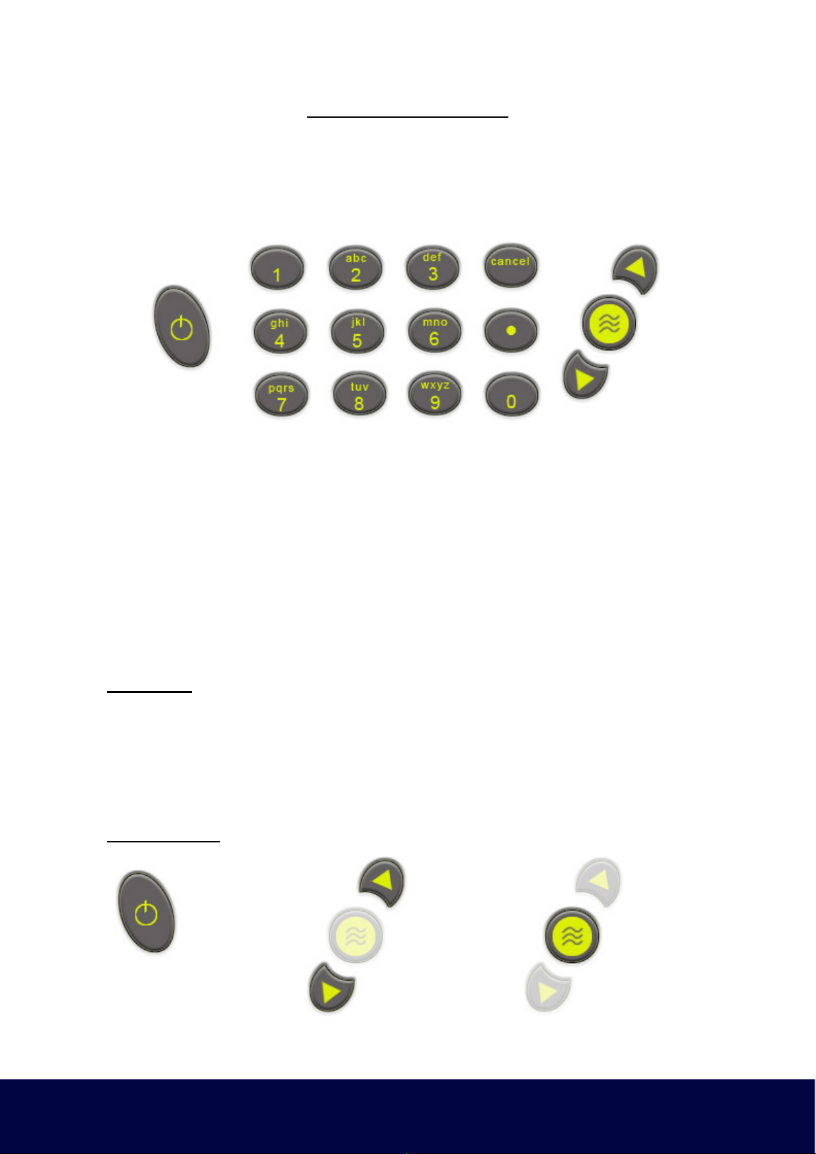
Switc on eac Outstation by pressing t e On/Off button. T e LED will flas Orange
t en Green (or Yellow/Red depending on battery status) to indicate t e unit is ready
for use.
To turn t e Outstations off, press and old t e On/Off button momentarily. T e LED
will lig t Red t en go off. W en t e LED as gone off, t e button can be released.
To c eck t e sensors are working correctly, connect t e eadp ones to t e Outstation
and listen w ile running your finger over t e sensor magnet. A clear crisp noise s ould
be eard.
Deploy eac sensor on a water pipe fitting eit er side of t e suspected leak position.
T e sensor as a strong magnet t at will enable it to remain in position on steel/iron
fittings.
Always ensure t e contact point is free from dirt so t at t e magnet makes a good
contact. We recommend t e use of a wire brus to clean t e pipe/valve/ ydrant fitting
prior to attac ing t e sensor.
Outstation LED Functions:
T e Outstation incorporates an LED, w ic provides t e following information:
During charge:
T e LED flas es red at t e start of c arging. W en t e c arging current starts to
fall, t e LED indication c anges to a yellow flas . W en c arging is complete, t e
LED will flas green.
During deployment:
W en t e unit is on and performing normally, t e LED flas es Green briefly once
a second. To indicate battery status t e LED will c ange from Green to Yellow
and Red. Wit t e LED flas ing Yellow, t e battery is OK. A Red flas ing LED in-
dicates t e battery requires immediate c arging.
If t e Outstation is off and t e system is not on c arge, t e LED is off.
Flexibility, Efficiency, Simplicity

8
Operating the Basestation
T e Basestation as an alp a-numeric keypad, similar to t at of a mobile p one. Keys
include a full stop, cancel, enter and up/down arrows. Navigation t roug t e menus
uses combinations of t ese keys. Most functions can be selected by t e number dis-
played on screen.
Moving around t e system is done via t e numeric keys. Eac page, function and
menu as a corresponding key to select t at page, function or menu. T e relevant key
to select is displayed on t e screen.
• T e up/down arrows select items wit in a list and move t e cursor on t e grap .
• Numbers 0—9 are used to select t e required menu or function.
• Enter accepts any c anges or saves current settings
• Cancel disregards any c anges and moves to previous page or menu.
Text Mode:
Entering text is similar to enter text on a mobile p one. Pressing key 2 several times
toggles between 2, A, B and C. Key 3 toggles t roug 3, D, E and F and so fort . Key
0 enters a space and . enters a full stop. T e arrow keys enter a < or > respectively.
Key 1 only enters t e number 1, t ere is no text function.
Function Keys:
Flexibility, Efficiency, Simplicity
On / Off Key Arrow Keys Enter Key

9
Correlate
Selecting Correlate (key 1) from t e main screen opens t e correlation screen. Wit
t e Outstations deployed and turned on, press t e Enter key to start t e correlation.
Correlation can be stopped at any time by pressing t e Enter key a second time.
Press Enter key for Correlation Set-up
Press Enter again to start Correlation
Press Enter a t ird time to stop Correlation.
Flexibility, Efficiency, Simplicity

10
Correlation Setup
T e Stations to be used for Correlation are selectable.
Flexibility, Efficiency, Simplicity
Table des matières
Autres manuels Palmer Instrument de mesure
Manuels Instrument de mesure populaires d'autres marques

Endress+Hauser
Endress+Hauser Proline Promag 50 Caractéristiques techniques

Siemens
Siemens SITRANS F Coriolis FCT030 Manuel de la liste des pièces

KLINGER
KLINGER CMF V Series Manuel utilisateur

EXFO
EXFO FTB-2 Manuel d'exploitation et d'entretien

Keysight
Keysight M8290A Manuel utilisateur

ADTEK
ADTEK MW-5 Manuel utilisateur


