
Ormazabal cpg.0 lite Manuel d'instructions

LIB
cpg.0 lite
GIS medium-voltage switchgear, gas
insulated, up to 24 kV, in accordance with
IEC Standard
General instructions
IG-310-EN, version 01, 31/03/2021

In view of the constant evolution in standards and design, the characteristics of the elements contained in this manual are subject
to change without prior notice. These characteristics, as well as the availability of components, are subject to confirmation by
Ormazabal.
CAUTION!
When medium-voltage equipment is operating, certain components are live, other parts may be in movement and some may
reach high temperatures. Therefore, the use of this equipment poses electrical, mechanical and thermal risks.
In order to ensure an acceptable level of protection for people and property, and in compliance with applicable environmental
recommendations, Ormazabal designs and manufactures its products according to the principle of integrated safety, based on
the following criteria:
• Elimination of hazards wherever possible.
• Where elimination of hazards is neither technically nor economically feasible, appropriate protection functions are
incorporated in the equipment.
• Communication about remaining risks to facilitate the design of operating procedures which prevent such risks,
training for the personnel in charge of the equipment, and the use of suitable personal protective equipment.
• Use of recyclable materials and establishment of procedures for the disposal of equipment and components so
that once the end of their service lives is reached, they are duly processed in accordance, as far as possible, with the
environmental restrictions established by the competent authorities.
Consequently, the equipment to which the present manual refers complies with the requirements of section 11.2 of Standard
IEC 62271-1. It must therefore only be operated by appropriately qualified and supervised personnel, in accordance with the
requirements of standard EN 50110-1 on the safety of electrical installations and standard EN 50110-2 on activities in or near
electrical installations. Personnel must be fully familiar with the instructions and warnings contained in this manual and in other
recommendations of a more general nature which are applicable to the situation according to current legislation[1].
The above must be carefully observed, as the correct and safe operation of this equipment depends not only on its design but also
on general circumstances which are in general beyond the control and responsibility of the manufacturer. More specifically:
• The equipment must be handled and transported appropriately from the factory to the place of installation.
• All intermediate storage should occur in conditions which do not alter or damage the characteristics of the equipment
or its essential components.
• Service conditions must be compatible with the equipment rating.
• The equipment must be operated strictly in accordance with the instructions given in the manual, and the applicable
operating and safety principles must be clearly understood.
• Maintenance should be performed properly, taking into account the actual service and environmental conditions in
the place of installation.
The manufacturer declines all liability for any significant indirect damages resulting from violation of the guarantee, under any
jurisdiction, including loss of income, stoppages and costs resulting from repair or replacement of parts.
Warranty
The manufacturer guarantees this product against any defect in materials and operation during the contractual period. In the
event that defects are detected, the manufacturer may opt either to repair or replace the equipment. Improper handling of this
equipment and its repair by the user shall constitute a violation of the guarantee.
Registered Trademarks and Copyrights
All registered trademarks cited in this document are the property of their respective owners. The intellectual property of this manual
belongs to Ormazabal.
[1] For example, in Spain the “Regulation on technical conditions and guarantees for safety in high-voltage electrical installations” – Royal Decree
337/2014 is obligatory.

IG-310-EN version 01; 31/03/2021 3
General instructions
cpg.0 lite: GIS medium-voltage switchgear,
gas insulated, up to 24 kV,
in accordance with IEC Standard
Contents
Contents
1. General description ...................................................4
1.1. Models ......................................4
1.2. Standards applied............................4
1.3. Main components ...........................5
2. Technical characteristics..........................................11
2.1. Electrical ratings ............................11
2.1.1. Name plate .................................12
2.2. Mechanical ratings ..........................13
2.2.1. Dimensions.................................13
2.3. IP rating ....................................13
3. Normal service conditions(a) ....................................14
4. Handling and transport...........................................15
4.1. Transport conditions ........................15
4.2. Lifting means ...............................15
5. Storage......................................................................17
6. Installation ...............................................................18
6.1. Unpacking the equipment ..................18
6.2. List of assembly materials supplied ..........18
6.3. Minimum installation distances..............19
6.4. Cable connection trench ....................19
6.4.1. Recommended dimensions .................20
6.5. Fixing to floor...............................21
6.6. Connecting cubicles ........................22
6.7. Cable connection ...........................23
6.8. Equipment earthing ........................24
7. Operations sequence...............................................25
7.1. Disconnector function operation sequence
(cpg.0 lite-s) ................................25
7.1.1. Manual feeder disconnector operation ......26
7.1.2. Manual earthing switch operation ...........30
7.1.3. Dielectric test for the cables .................34
7.2. Circuit-breaker function operation sequence
(cpg.0 lite-v) . . . . . . . . . . . . . . . . . . . . . . . . . . . . . . . .39
7.2.1. Circuit-breaker operation....................40
7.2.2. Manual earthing switch operation ...........45
7.2.3. Dielectric test for the cables .................45
7.3. Busbar coupling function operation
sequence (cpg.0 lite-c) ......................52
7.3.1. Busbar coupling operation ..................53
7.3.2. Busbar decoupling operation................59
7.3.3. Right busbar earthing operation.............63
7.3.4. Right busbar earthing opening operation....69
7.3.5. Left busbar earthing operation . . . . . . . . . . . . . .73
7.3.6. Left busbar earthing opening operation .....79
8. Safety elements........................................................83
8.1. ekor.ivds voltage detectors .................83
8.2. Locking with padlock .......................83
8.2.1. Locking with key lock .......................83
8.3. Interlocks ...................................84
9. Maintenance.............................................................85
9.1. Voltage indicator test .......................85
9.2. Preventive maintenance of circuit-breakers ..86
10. Spares and accessories ............................................87
11. Environmental information ....................................88
11.1. Sulphur hexafluoride SF6....................88
11.2. Recyclability ................................88

IG-310-EN version 01; 31/03/2021
4
General description General instructions
cpg.0 lite: GIS medium-voltage switchgear,
gas insulated, up to 24 kV,
in accordance with IEC Standard
1. General description
The cpg.0 lite switchgear is made up of a series of GIS
cubicles, gas-lled, for primary distribution in medium-
voltage networks up to 24 kV.
1.1. Models
Model Function
cpg.0 lite-v Circuit-breaker
cpg.0 lite-c Longitudinal busbar coupling
cpg.0 lite-s Disconnector
Table 1.1. cpg.0 lite cubicle models
1.2. Standards applied
Standard Description
IEC 62271-1 Common specications for high-voltage switchgear standards
IEC 62271-200 Alternating current metal-enclosed switchgear and controlgear for rated voltages above 1 kV and up to and
including 52 kV
IEC 62271-100 Alternating current circuit-breakers
IEC 62271-102 Alternating current disconnectors and earthing switches
IEC 61243-5 Voltage presence indicating relays
IEC 60529 IP ratings for enclosures
Table 1.2. Standards applied

IG-310-EN version 01; 31/03/2021 5
General instructions
cpg.0 lite: GIS medium-voltage switchgear,
gas insulated, up to 24 kV,
in accordance with IEC Standard
General description
1.3. Main components
1Busbar compartment
2Gas tank
3Gas pressure relief duct
4Cable compartment
5Control compartment
6Driving mechanisms compartment
Figure 1.1. Main elements cpg.0 lite cubicles

IG-310-EN version 01; 31/03/2021
6
General description General instructions
cpg.0 lite: GIS medium-voltage switchgear,
gas insulated, up to 24 kV,
in accordance with IEC Standard
Gas tank
This is a sealed compartment, made of stainless steel and
sealed for life, which houses the switching and breaking
switchgear, with the gas as the insulating medium.
Depending on the function the cubicle was designed for, it
may contain some of the following components inside:
• Three-position disconnector.
• Internal busbar and connections.
• Vacuum circuit-breaker.
Connection to the busbar is possible via top bushings.
Connection to the medium-voltage cables is made with the
bottom bushings.
The gas pressure is tested in each cubicle by means of a
temperature-compensated pressure switch with a volt-
free contact, allowing it to be used as aremote alarm or
blocking/trip for the position. Figure 1.2. Example of bushing position in gas tank (1)
Busbar compartment
The busbar compartment, designed to withstand an internal
arc inside, meeting the criteria of Annex A of Standard
IEC 62271-200, class IAC: AFL/AFLR, is located at the top
of the cubicle, separate from the gas tank. It is made from
sheet metal, oering the degree of protection necessary for
the connecting device.
The main busbar is insulated with solid material, which is
screened and earthed.
Toroidal-core current transformers and/or plug-in voltage
transformers can also be installed, thus avoiding the need
for metering cubicles.
Figure 1.3. Busbar compartment detail
IG-310-EN version 01; 31/03/2021 7
General instructions
cpg.0 lite: GIS medium-voltage switchgear,
gas insulated, up to 24 kV,
in accordance with IEC Standard
General description
Cable compartment
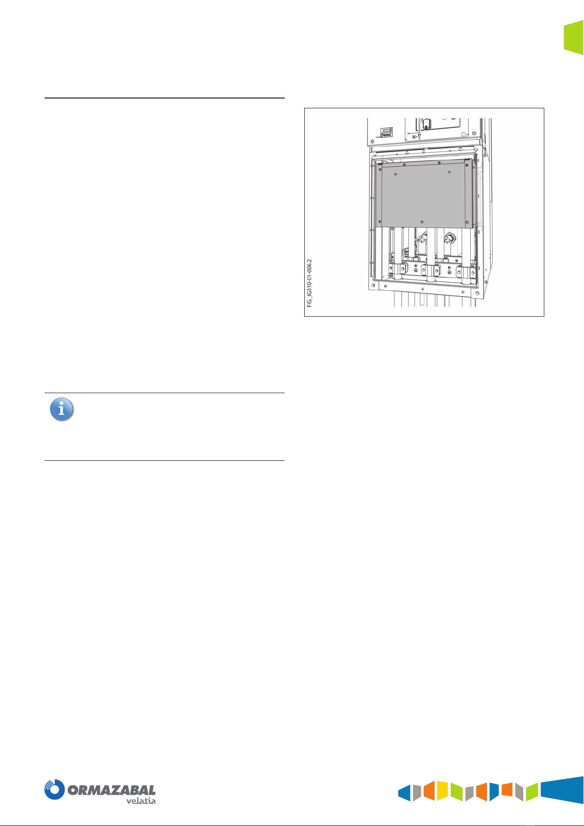
Located in the bottom part of the cubicle, this has a cover,
interlocked with the earthing of the power cables, which
allows front access to the medium-voltage cables. This
compartment is prepared to withstand an internal arc up
to 25 kA - 1 s, meeting the criteria of Annex AA of Standard
IEC 62271-200, class IAC: AFL/AFLR.
In the most complete case, the base can house the following
components:
• Internal arc protection kit in cable compartment.
• Two symmetrical screened connectors with reinforced
connection (screwable) per phase, or three compact
screened connectors with reinforced connection
(screwable) per phase.
• Cable clamps for the medium-voltage cables. Range of
cable diameters admitted: from 36 to 52 mm. For other
values, please ask Ormazabal.
• Earthing bars for cable connectors (optional).
• Toroidal-core current transformers.
• Voltage transformers with connection via medium-
voltage cable.
All the elements making up the enclosure are earthed
by means of a conductor consisting of a copper bar,
sized to withstand the rated short-time current. This is
located in the base, meaning it does not need to be
dismantled in order to insert or remove a cable and its
corresponding termination.
Figure 1.4. Detail of internal arc protection kit in cable compartment

IG-310-EN version 01; 31/03/2021
8
General description General instructions
cpg.0 lite: GIS medium-voltage switchgear,
gas insulated, up to 24 kV,
in accordance with IEC Standard
Exterior cable connections (bushing)
The cpg.0 lite cubicles have bushing on the front for
medium-voltage cable connection. These are made of
epoxy resin and can, thanks to their design, withstand the
current transformers. They are duly screened and designed
in line with Standard EN 50181, type "C".
They allow conductors to be connected via screwable
T-type connectors of any manufacturer.
The cable clamps in the cable compartment hold the
cables at their input to the cubicle and prevent the
connector and bushing combination from supporting
the weight of the cable. If cable input/output is via
a trench more than 2 m deep, the cables must be
fastened with additional cable clamps, depending on
the depth of the trench and the cable cross-section
(weight), in order to prevent the connector and
bushing combination from supporting the weight of
the cable.
Figure 1.5. Cable compartment

IG-310-EN version 01; 31/03/2021 9
General instructions
cpg.0 lite: GIS medium-voltage switchgear,
gas insulated, up to 24 kV,
in accordance with IEC Standard
General description
Gas pressure relief duct
The entire cubicle is prepared to withstand an internal arc
in the tank up to 25 kA - 1 s, meeting the criteria of Annex
AA of Standard IEC 62271-200, accessibility class IAC: AFL/
AFLR.
1Gas pressure relief membrane
2Gas vent from cable compartment
Figure 1.6. Pressure relief membrane and gas vent detail
A metal duct can take the gases produced by an internal arc
toward the top of the cubicle from the gas tank and cable
compartment.
Figure 1.7. Gas pressure relief duct (1)
Control compartment
Placed at the top of the cubicle and separate from the
medium-voltage area, this is ready for installation of the
metering equipment and protection relays. It contains
the terminal block with the control signals duly identied
in accordance with the wiring diagram provided with
the equipment. All the connections between the driving
mechanisms compartment and the control box are made
via connectors, which makes the assembly more exible,
and allows the control box to be assembled and connected
on site in a straightforward, direct way.
Figure 1.8. Control compartment detail
IG-310-EN version 01; 31/03/2021
10
General description General instructions
cpg.0 lite: GIS medium-voltage switchgear,
gas insulated, up to 24 kV,
in accordance with IEC Standard
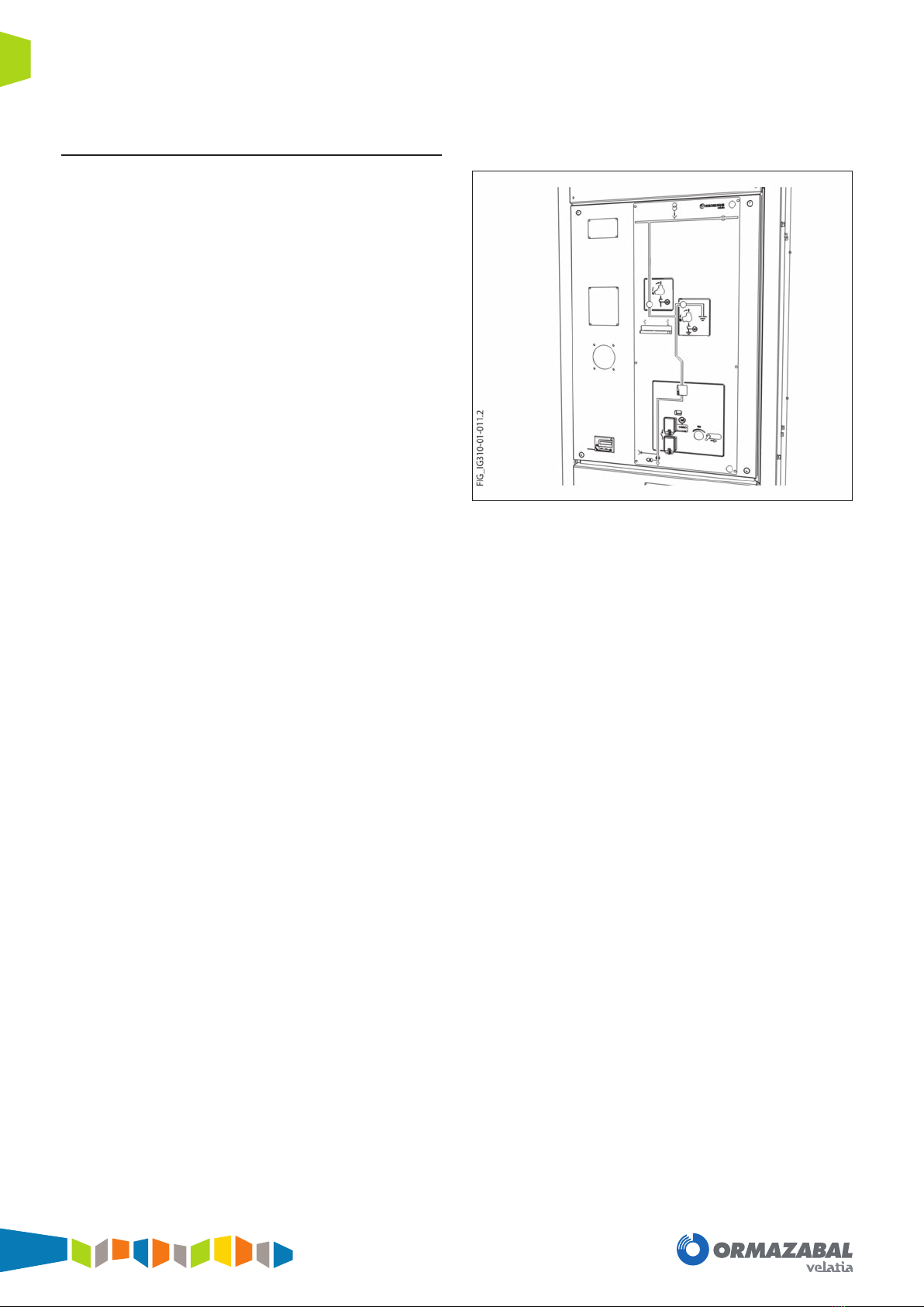
Driving mechanism
In addition to a mimic diagram customised for each type of
function, this has the driving elements in its middle section:
disconnector/earthing switch and circuit-breaker driving
mechanisms, circuit-breaker opening/closing pushbuttons,
status indicators, groove for access of the spring charging
lever, etc.
Figure 1.9. Example of driving mechanism area
Ce manuel convient aux modèles suivants
3
Table des matières
Autres manuels Ormazabal Changer


