olympia electronics GR-7500 Manuel utilisateur

GR-7500 Web UI User Manual
The present document compiles a detailed presentation and
documentation of the web app that accompanies each GR-7500 panel
for addressable emergency luminaires. It involves the user’s flow and
navigation throughout the website, providing an elaborate account of
each page’s controls and functionality.

Table of Contents
1. Introduction.............................................................................................................3
2. Application..............................................................................................................3
2.1. Home Screen ...................................................................................................3
2.2. Sign In.................................................................................................................4
2.3. Quick-access Options ....................................................................................5
2.4. User Menu .........................................................................................................6
2.4.1. Points ...........................................................................................................6
2.4.2. Zones ...........................................................................................................6
2.4.3. Check..........................................................................................................7
2.4.4. Luminaire Commands .......................................................................... 12
2.4.5. Panel Network........................................................................................ 15
2.4.6. System Version........................................................................................ 16
2.4.7. Technician Info....................................................................................... 17
2.5. Technician Menu.......................................................................................... 17
2.5.1. Settings..................................................................................................... 17
2.5.2. Test ............................................................................................................ 20
2.5.3. Setup ........................................................................................................ 23
2.5.4. Panel Network........................................................................................ 26
2.6. Additional Notes........................................................................................... 28
2.7. Sign Out .......................................................................................................... 29
3. Epilogue ................................................................................................................ 30
1. Introduction
Web UI is a complimentary feature of the GR-7500 panel, designed to
monitor and configure a panel, through any device with browser support
that is also connected to the same network as the panel. It is built as a
single-page-application that aims at the seamless transition throughout its
functionality, and at a dynamic data-flow update.
It supports both available access levels, User and Technician, and covers
all monitoring and configuration options that are found within the panel’s
GUI. The web application is unique to each panel and can be accessed
using the panel’s IP address as the website’s URL.
This user manual is structured using static screenshots each depicting a
different route within the application, detailing all the elements that are of
interest and use to the user.
2. Application
2.1. Home Screen
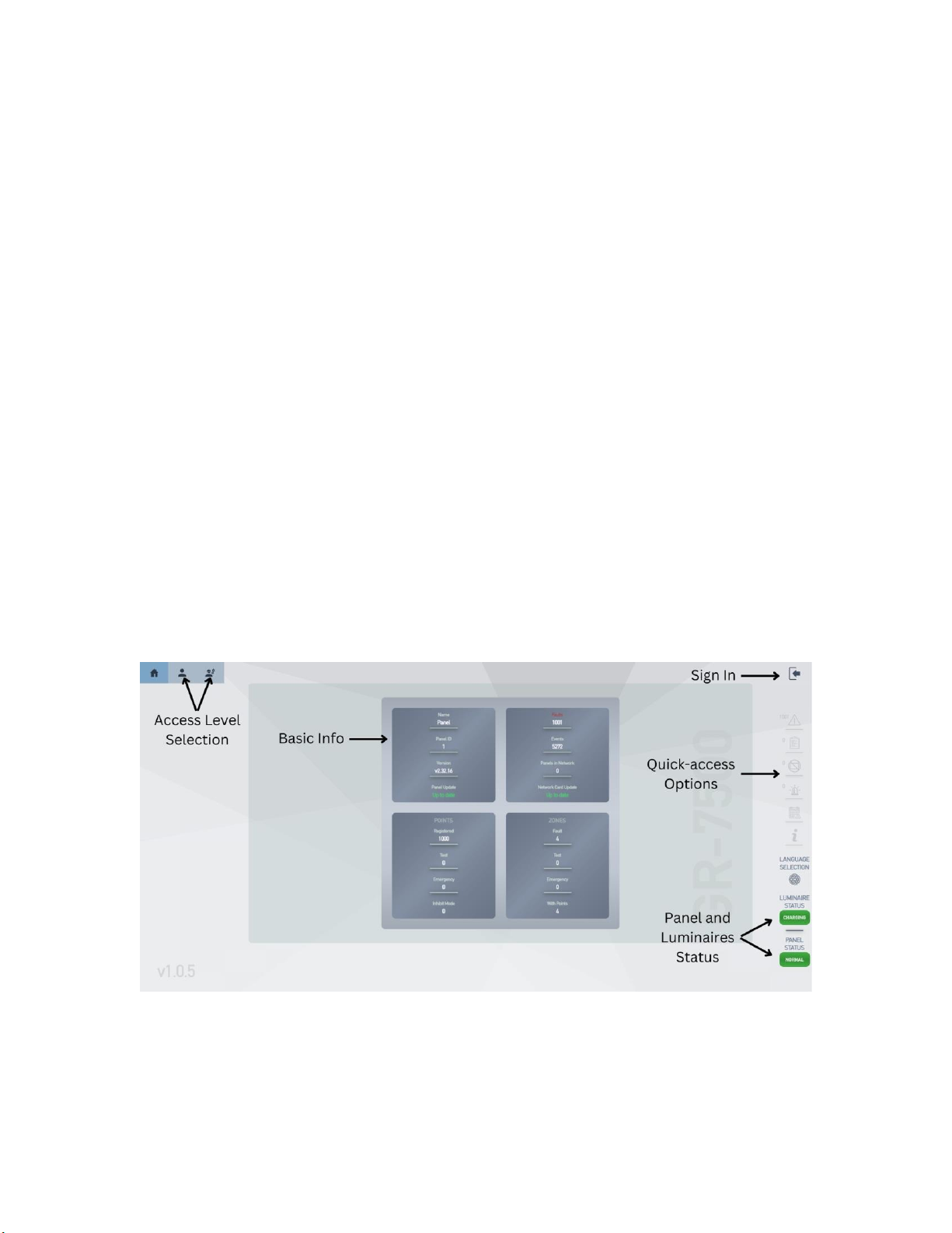
The home screen is the initial and main view on the user’s device. It consists
of several elements with different functions. The center of the view holds all
the basic information regarding the panel and is broken down to four
individual frames. The top-leftmost contains the panel’s name, version and
update status. The top-rightmost shows the number of faults and overall
events within the panel and the network card’s update status. The bottom-
leftmost holds information about the connected points and the bottom-
rightmost about the panel’s connection zones.
The top-left section of the view affords the user access to the User (left) and
Technician (right) menu, provided they Sign In with the appropriate set of
credentials. Across the same height, on the top-right corner, is the Sign In
option.
The center-right part is dedicated to the quick-access options, which are
unlocked after the user has successfully logged in. Each option contains an
array of (from top to bottom) faults, points in test, points in inhibit, points in
emergency, events and a table with rudimentary panel information.
The bottom-right section consists of a control for language selection
between English and Greek and a set of color-changing blocks depicting
the panel and luminaires’ status, depending on their function or lack
thereof.
2.2. Sign In
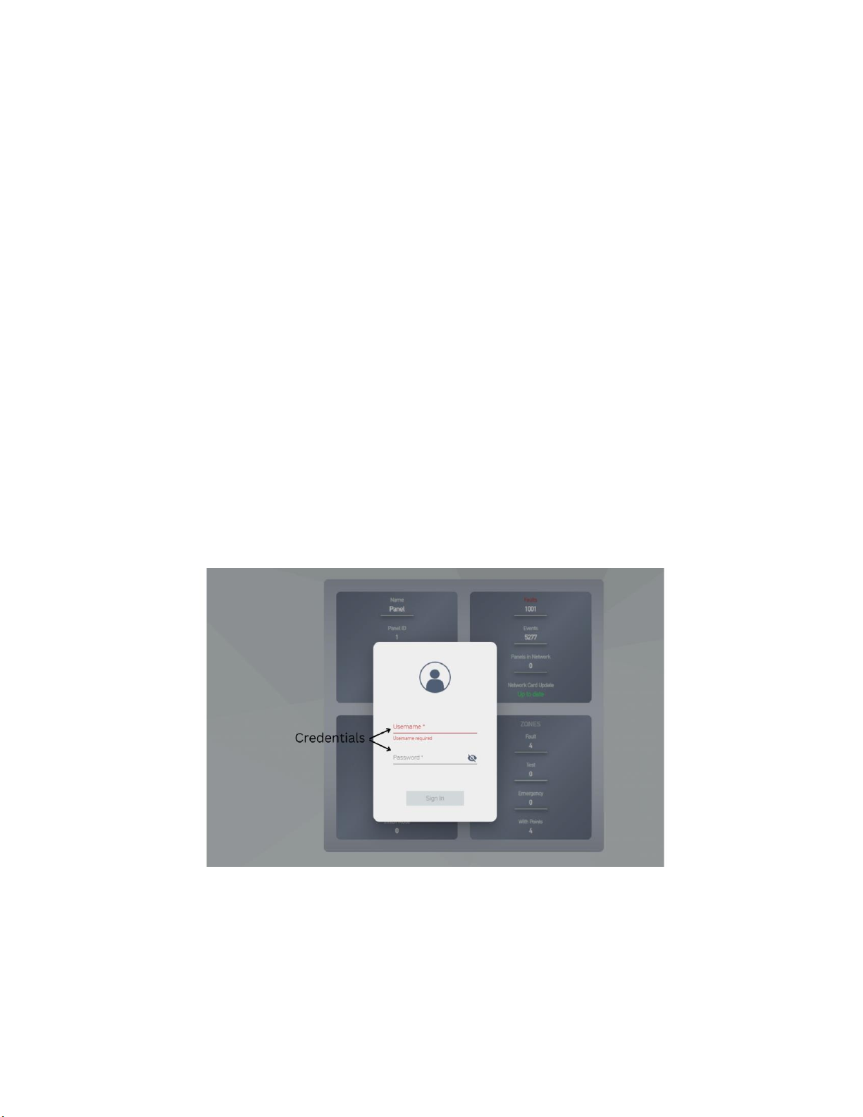
The Sign In option creates an overlaid card that contains a fully validated
form, allowing up to five consecutive attempts at signing in. Depending on
the provided set of credentials, the user will be logged in the respective
menu. After successfully gaining access, the user will not be redirected to
the appropriate menu. They will manually have to navigate to their target
area.

2.3. Quick-access Options
Each quick-access option creates an overlaid table with information
regarding the panel’s faults, points in test, points in inhibit, points in
emergency, events and information. As shown in the image above, for
example, the panel’s faults and all tables’ data are arranged with sorting
and pagination capabilities. This specific table also contains the option to
reset the faults within the table for a fresh view.
Another example is the preceding image with information about the
panel’s various events, from signing in and out, to commencing luminaire
tests and updating the panel or the network card, to a maximum of 6000
registered events.

2.4. User Menu
2.4.1. Points
The above view contains rudimentary information about all the luminaire
points that are associated with the current panel. The user is given the
option to inspect each point for further information, through each point’s
accompanying button.
2.4.2. Zones
This is a submenu that consists of four (4) different views, each one
displaying a table with basic information about the panel’s zones. Namely,
the first view holds the number of points registered to each zone; the
second view holds information about those zones that contain points that
are being tested; the third view, similarly, holds information about those
zones with points that are in emergency operation; the fourth view lists
those zones with points that are in fault.
2.4.3. Check
The check menu option is structured with a submenu of controls that
monitor the proper function of each essential part within the panel.
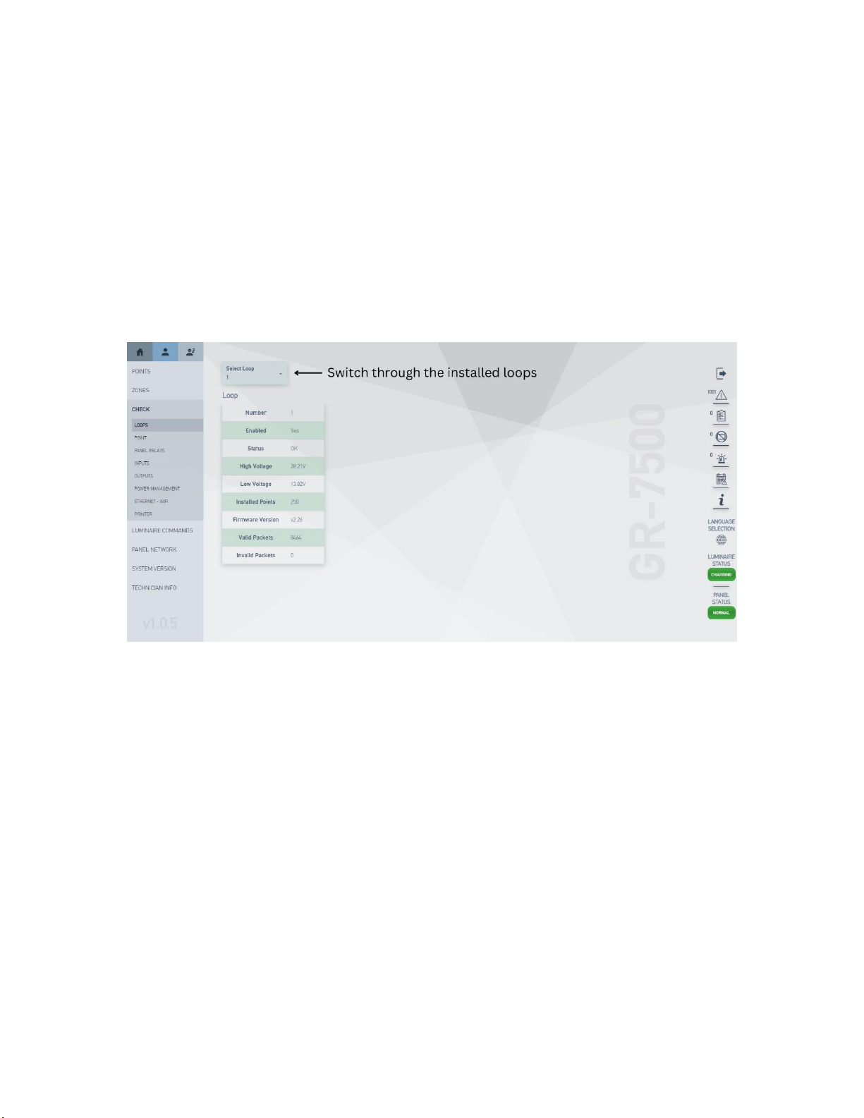
2.4.3.1. Loops
This view consists of a simple table with all the necessary information
regarding the function of a control loop, along with the option to select
among the panel’s installed loops.
2.4.3.2. Point
The following view concerns each luminaire’s essential information for
identification and maintenance, as it can be directly compared to the
expected values for each measurement field and evaluate the functioning
capabilities of the selected luminaire. The user is given the option to switch
through all registered points for each loop and the information is updated
after each selection.

Additionally, the view contains a button that creates an overlay window
with point specific commands. These commands are unicast to the
selected luminaire and are shown below.
2.4.3.4. Panel Relays
The following view displays the status, logic and applicability of all the
panel’s relays; relay fault, relay aux, relay operation, relay supply, output 1,
and output 2.
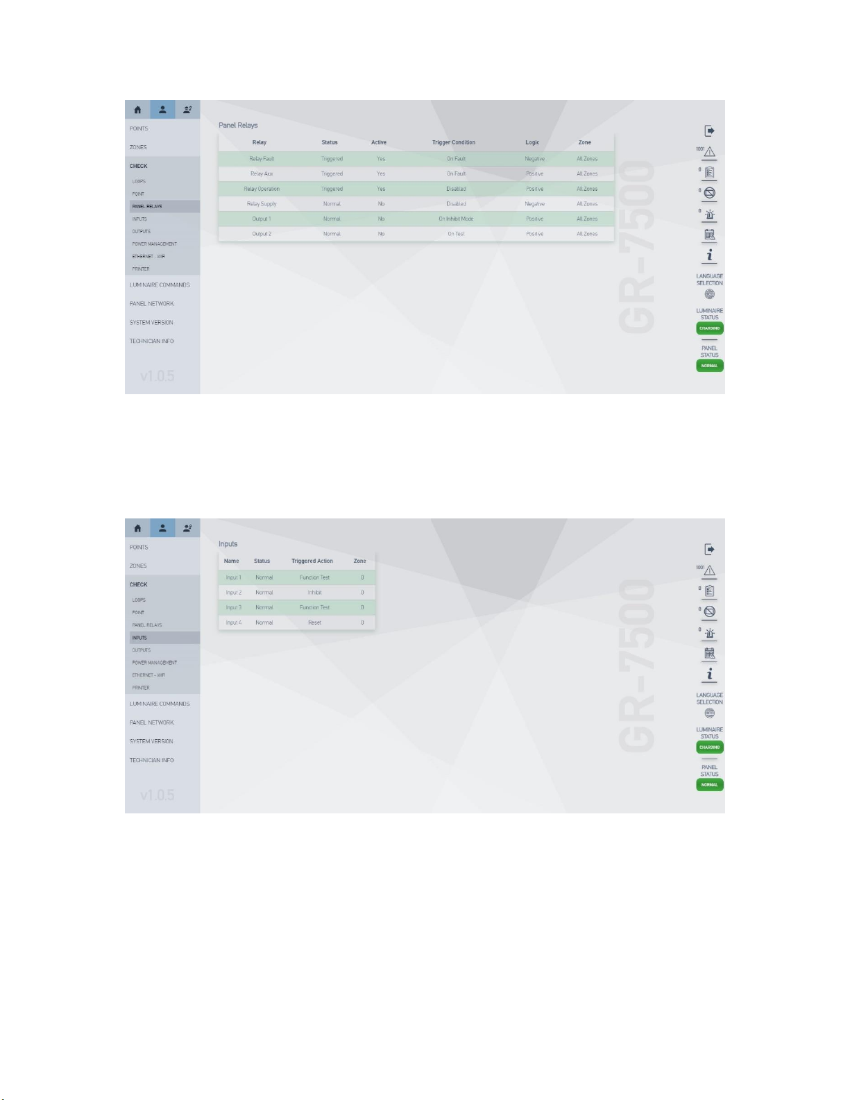
2.4.3.5. Inputs
The view below represents the status of the four (4) inputs the panel
possesses.
2.4.3.6. Outputs
The view below represents the status of the two (2) outputs the panel
possesses.
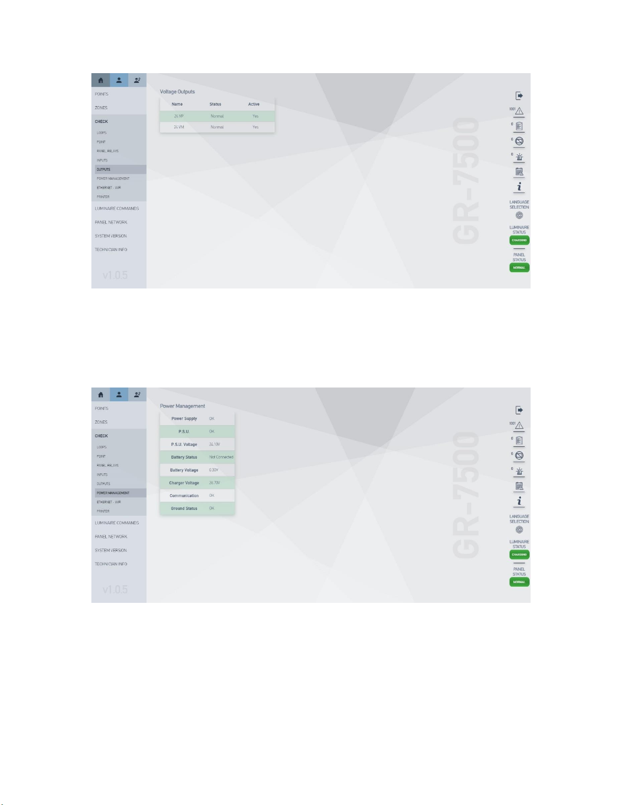
2.4.3.7. Power Management
This item is responsible for the display of core power supply information,
either through the main network or through the panel’s pre-installed
batteries, vital to the unit’s functionality in the event of insufficient main
power.
2.4.3.8. Ethernet –WiFi
This view concerns the user with the panel’s basic connectivity information,
such as its MAC and IP addresses, subnet mask, default gateway and WPS
configuration values offering the option to switch through the display of
wired or wireless connection information.
Table des matières
Autres manuels olympia electronics Équipements de sécurité


Manuels Équipements de sécurité populaires d'autres marques

Innova
Innova Xtirpa Mode d’emploi

bolle SAFETY
bolle SAFETY B810 Manuel utilisateur

SHENZHEN FANHAI SANJIANG ELECTRONICS
SHENZHEN FANHAI SANJIANG ELECTRONICS A9060T Manuel utilisateur

Hiltron security
Hiltron security POWER8E Mode d’emploi

Hatco
Hatco B-950P Manuel utilisateur

Sitec
Sitec TX MATIC Manuel utilisateur