Oliver 5240 Manuel utilisateur

1
Oliver 5240 Owner’s Manual

2
Oliver 5240 Owner’s Manual
Thank you for your purchase of a genuine Oliver woodworking
machine. Oliver Machinery has made every attempt to provide a
machine that is safe and durable. All Oliver products are guaranteed,
to the original customer, to be free from defects for one year from the
date of purchase. Oliver Machinery will repair or replace, at its option,
any component that fails under normal use. Please note that the
customer is responsible for returning the failed component to Oliver
Machinery prepaid for inspection. This warranty does not cover
damages caused by misuse, accident, unauthorized repair, alteration
or improper maintenance.
ead this manual thoroughly before operating the machine. Oliver
Machinery disclaims any liability for machines that have been altered
or abused.
WARRANTY
WARNING

3
Oliver 5240 Owner’s Manual
TABLE OF CONTENTS
1. Safety ................................................................................................................................................4
1.1 General Woodworking Safety ules ............................................................................................4
1.2 Specific Woodworking Safety ules for Double Side Jointing Planers.......................................4
2. Machine Specifications .................................................................................................................... 5
3. Setup................................................................................................................................................ 6
3.1 Unpacking the Machine .............................................................................................................. 6
3.2 Machine Preparation and Setup .................................................................................................7
3.3 Installation of Dust Collection....................................................................................................8
3.4 Electrical Connections ............................................................................................................... 9
4. Explanation of Controls ................................................................................................................. 10
5. Operating the Double Side Jointing Planer ................................................................................... 12
5.1 Digital Controller Operation......................................................................................................13
5.1.1 Changing Units of Measure ............................................................................................ 14
5.1.2 Setting the Controller to a Specific Thickness ............................................................... 15
5.1.3 Calibrating the Digital Thickness Controller ................................................................. 16
5.2 Changing Feed Speed ............................................................................................................... 18
5.3 Adjusting Cutting Thickness/Setting Depth of Cut................................................................. 19
5.4 eplacing Knives in the Cutterheads....................................................................................... 20
5.4.1 Procedure for Top Cutterhead........................................................................................ 20
5.4.2 Procedure for Bottom Cutterhead ................................................................................. 21
5.5 Bed oller Adjustment.............................................................................................................. 23
5.6 Lower Cutterhead Height Adjustment .................................................................................... 24
5.7 Chipbreaker Height Adjustment ..............................................................................................25
5.8 Pressure Bar Adjustment ..........................................................................................................25
5.9 Outfeed oller Height Adjustment ..........................................................................................25
6. Maintenance .................................................................................................................................. 26
7. Trouble-Shooting ...........................................................................................................................27

4
Oliver 5240 Owner’s Manual
Safety
1. SAFETY
ead this manual completely and observe all warning labels on the machine. Oliver Machinery has made every attempt to
provide a safe, reliable, easy-to-use piece of machinery. Safety, however, is ultimately the responsibility of the individual
machine operator. As with any piece of machinery, the operator must exercise caution, patience, and common sense to
safely run the machine. Before operating this product, become familiar with the safety rules in the following sections.
Feel free to contact your local dealer with any safety concerns.
1.1 General Woodworking Safety Rules
1. ead the owner’s manual completely before operating the machine.
2. Observe the warning labels on the machine.
3. Use the machine for its intended purpose only.
4. Obtain training before operating the machine.
5. Do not operate this machine while under the influence of drugs, alcohol or medication.
6. Make certain the machine is electrically grounded and that all electrical connections are secure.
7. Wear eye protection and hearing protection when operating this machine.
8. Keep the floor and area around the machine free of sawdust, oil, scrap materials, rags or other items to minimize the
risk of slippage and/or injury.
9. Make certain the area around the machine is well lighted.
10. Utilize guards and other safety features whenever possible. Keep all guards and safety features in good working order.
11. Do not wear loose clothing, neckties, rings, watches, bracelets or other items that could become caught in the ma-
chine. Keep long hair contained, and keep shirtsleeves above the elbow.
12. Attach adequate dust collection to the machine, and wear dust protection masks when appropriate.
13. Never leave the machine running unattended. Always wait until the machine has come to a complete stop before
leaving it.
14. emove all wrenches and adjustment tools prior to starting the machine.
15. Disconnect the machine from power before making any adjustments.
16. Use extension tables or a helper when working with large pieces.
1.2 Specific Woodworking Safety Rules for
Double Side Jointing laners
1. Make certain that the knives are sharp, rust free and in good working order.
2. Always feed stock from the infeed side to the outfeed side. Never feed stock backwards through the machine.
3. Never place your hands under the workpiece. They could become trapped between the table and the workpiece.
4. Do not try to remove a workpiece after the machine has started to feed. Instead, turn off the machine, raise the
carriage and then remove the piece.
5. Do not feed stacked material.
6. Turn the machine off before clearing chips and shavings.
7. Do not feed wood that contains loose knots, nails, staples or other foreign materials.

5
Oliver 5240 Owner’s Manual
Table 1
2 MACHINE SPECIFICATIONS
This machine was designed to cut hardwoods, softwoods, and most panel products. Do not use this machine for any other
purposes. Table 1 describes the specifications of the Oliver 5240 double side jointing planer.
Specifications 5240
Bottom Cutterhead Motor 20 HP
Top Cutterhead Motor 15 HP
Feed Motor 3 HP
Table Height Motor 1/2 HP
Maximum Stock Width 25”
Maximum Stock Thickness 7.75”
Minimum Stock Length 12”
Feed Speed Variable, 21-66 FPM
Knife Size 14.6 x 14.6 x 2.5 mm
Knives per Cutterhead 164
Electrical 3 Phase, 220/440 V
Gross Weight 7900 lbs.
Machine Specifications
Figure 1
An overall dimensional sketch of the assembled 5240 is given in Figure 1.
Side ViewFront View
105
37 1
274
66
32
3
4
1
2
DIMENSIONS All dimensions in inches.

6
Oliver 5240 Owner’s Manual
Figure 2 Figure 3
Figure 1
. SETUP
Before unpacking the machine, check it carefully for signs
of shipping damage. If damage is suspected, contact your
dealer immediately.
3.1
Unpacking the Machine
Carefully uncrate the machine. Again, inspect the unit for
signs of shipping damage. If damage is found, contact
your dealer immediately. For protection against shifting,
the double side jointing planer was bolted to the shipping
pallet in four places (see Figure 1). emove these bolts
before lifting the planer off the pallet.
The machine may be lifted from the pallet by forklift or
crane (see Figure 2 and Figure ). etain all packaging
materials in case it becomes necessary to ship the machine
back to the dealer or to another site.
Setup

7
Oliver 5240 Owner’s Manual
Figure 4
3.2
Machine reparation and Setup
Situate the double side jointing planer on a smooth, level
surface. Install the leveling feet in the four corners of the
machine, as shown in Figure 4. Use a level to ensure that
the planers bed is level from front to back and left to right.
Note: Even if your shop floor is level, installation
of the leveling feet will improve stability and
reduce vibration.
A protective anti-rust agent was applied to the
non-painted cast iron and steel components of this double
side jointing planer. This should be removed with a soft
cloth and kerosene. Do not use paint thinner. Do not
allow the kerosene to come into contact with electrical
cords or connections.
Setup

8
Oliver 5240 Owner’s Manual
Setup
Figure 6
Figure 5
3.3
Installation of
Dust Collection
The Oliver 5240 double side jointing planer is equipped with
two 6” dust collection ports, one for each cutterhead. Make
certain to secure all dust hoses to the dust ports with hose
clamps or similar devices.
1. Attach a dust collection hose to the dust chute for the
bottom cutterhead. This chute is located at the lower
right side of the machine, as shown in Figure 5. The
operator may find it helpful to open the side door when
making this connection.
2. Attach a dust collection hose to the dust chute for the
top cutterhead. This chute is located at the top, rear of
the machine, as shown in Figure 6.
9
Oliver 5240 Owner’s Manual
Figure 7
Figure 8
Figure 9
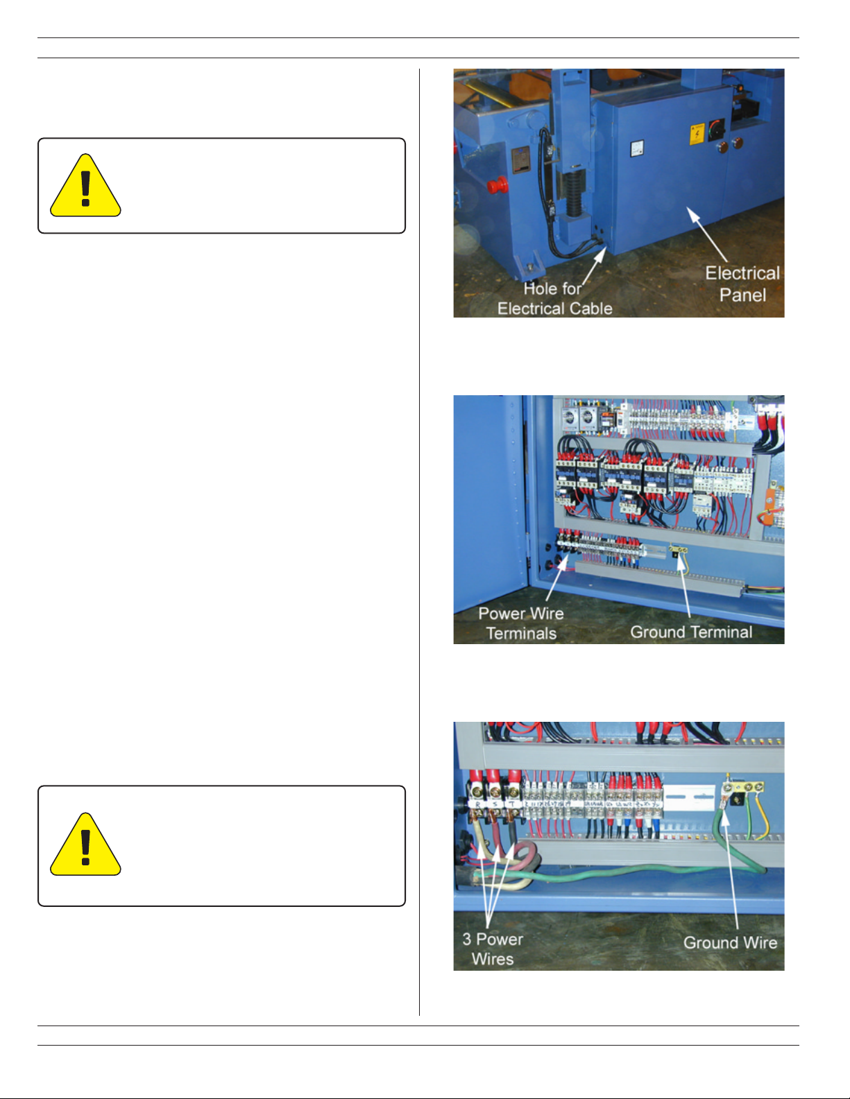
3.4
Electrical Connections
ELECTRICAL CONNECTION MUST
BE MADE BY QUALIFIED PERSONNEL
ONLY.
This double side jointing planer has been pre-wired to
accept 3-Phase, 208-230V. Maxi u current draw is
approxi ately 100 a ps. Oliver Machinery reco ends
the use of a 4-gauge, 4-conductor electrical cable.
1. The electrical connections are ade in the electrical panel
at the lower left side of the achine. See Figure 7.
2. Open the door of the electrical panel. Slide the electrical
cable through the hole at the lower left side of the
electrical box.
3. Connect the 3 power wires at the terminal block shown in
Figure 8. The ground wire ust be connected at the
grounding terminal block shown in Figure 8.
Note: If t e 3-P ase power in your s op consists of one
ig leg and two low legs, t en you must connect t e
ig leg to terminal T.
4. The properly installed electrical cable should look like
Figure 9.
5. Close the door to the electrical panel and secure it with
the handle.
Setup
MAKE CERTAIN THAT YOUR
MACHINE IS PROPERLY GROUNDED.
FAILURE TO DO SO CAN LEAD TO
INJURY OR DEATH.

10
Oliver 5240 Owner’s Manual
Explanation of Controls
Figure 10
4. EXPLANATION OF CONTROLS
This section is designed to be a quick overview of all the levers, handwheels, buttons, etc. on the Oliver 5240 double side
jointing planer. A general description of each item follows Figure 10. Detailed instructions on the use of these controls
can be found in Sections 3 and 5.
Table des matières
Autres manuels Oliver Raboteuse

Oliver
Oliver 0015 Manuel utilisateur

Oliver
Oliver 4420 Manuel utilisateur

Oliver
Oliver 10014 Manuel utilisateur

Oliver
Oliver 4470 Manuel utilisateur

Oliver
Oliver 5235 Manuel utilisateur

Oliver
Oliver 4455 Manuel utilisateur

Oliver
Oliver 4430 Manuel utilisateur

Oliver
Oliver 4420 Manuel utilisateur

Oliver
Oliver 4455 Manuel utilisateur

Oliver
Oliver 4430.201 M-4430 Manuel utilisateur


