Oilon RE 28 05 Manuel utilisateur

M8009 2147EN
25 October 2021
Installation and
operation manual
RE 28–48, RE 56–96


Contents
1 Introduction
1.1 Heat pumps covered in the manual........................................................... 3
1.2 Product description..................................................................................... 3
1.3 Instructions and diagrams...........................................................................4
1.4 Safety notice and warnings........................................................................ 4
1.5 Transportation and storage.........................................................................6
1.6 Scope of delivery........................................................................................ 7
1.7 Accessories................................................................................................. 8
2 Installation
2.1 Installation site.......................................................................................... 10
2.2 Dimensions, connections, and components............................................. 11
2.3 Modbus connection...................................................................................14
3 Installing temperature sensors
3.1 Outdoor temperature sensor.....................................................................15
3.2 DHW tank sensor......................................................................................15
3.3 Buffer tank sensor.....................................................................................16
3.4 Flow temperature sensor for heating circuit 1.......................................... 17
4 Commissioning
4.1 Configuring automation settings............................................................... 19
4.2 Starting the heat pump............................................................................. 19
4.3 Automation factory settings...................................................................... 20
4.4 Bleeding the system of air........................................................................22
5 Operation
5.1 Heat pump user interface......................................................................... 23
5.2 Commissioning menus..............................................................................25
5.3 Start page................................................................................................. 27
5.4 Heating circuit menu.................................................................................27
5.5 Heating curve............................................................................................28
5.6 Domestic hot water menu.........................................................................29
5.7 Changing the user level............................................................................30
5.8 Diagnostics menu......................................................................................31
5.9 Service menu............................................................................................ 31
5.10 Parameter list............................................................................................31
5.11 Resetting the heat pump.......................................................................... 32
5.12 Relay test.................................................................................................. 33
6 Cascade connection
6.1 Cascade connection..................................................................................36
M8009 2147EN 1 (74)

6.2 LPB bus configuration...............................................................................37
6.3 Shared brine circuit pump........................................................................ 39
6.4 Separate heat pump for DHW heating..................................................... 40
7 Technical data
7.1 Technical data...........................................................................................41
7.2 Compressor units......................................................................................45
7.3 Performance data......................................................................................46
7.4 EN 14285 Technical data sheets............................................................. 59
7.5 Operating conditions................................................................................. 63
7.6 Condenser circuit and evaporator pressure loss...................................... 65
7.7 Pumps....................................................................................................... 66
7.8 Temperature sensors................................................................................71
7.9 EU product data........................................................................................71
2 (74) M8009 2147EN

1 Introduction
1.1 Heat pumps covered in the manual
Model Item code Refrigerant
RE 28 05 RE2805 R-410A
RE 33 05 RE3305 R-410A
RE 38 05 RE3805 R-410A
RE 42 05 RE4205 R-410A
RE 48 05 RE4805 R-410A
RE 56 05 RE5605 R-410A
RE 66 05 RE6605 R-410A
RE 76 05 RE7605 R-410A
RE 84 05 RE8405 R-410A
RE 96 05 RE9605 R-410A
1.2 Product description
RE 05 heat pumps
RE 05 heat pumps come in two configurations: RE 28–48 heat pumps have a single
compressor unit, while RE 56–96 heat pumps have two compressor units. All RE heat
pumps include a control cabinet. The standard position of the control cabinet is on the
unit's left side, but it can be moved to the right side if needed.
RE 28–48 models
By default, the unit’s automation system has been configured for one domestic hot
water tank, one buffer tank for a heating circuit, and one heating circuit controlled by
a three-way valve. The automation system supports numerous other connections,
systems and accessories. Alternative system configurations are presented in separate
technical manuals for the automation system.
RE 56–96 models
The heat pump includes two compressor units, which can be used independently or
they can be joined together. The automation system has a separate controller and
separate electrical connections for each unit. If the units are used separately, they
operate independently of each other.
In standard two-unit deliveries, the units’ automation systems have been connected
for joint use (in a cascade configuration). In cascade systems, one of the heat pump
controllers operates as the master and controls the entire system, while the other, the
slave controller, operates under the master controller. The upper unit is the master unit
and the lower unit the slave unit.
M8009 2147EN 3 (74)
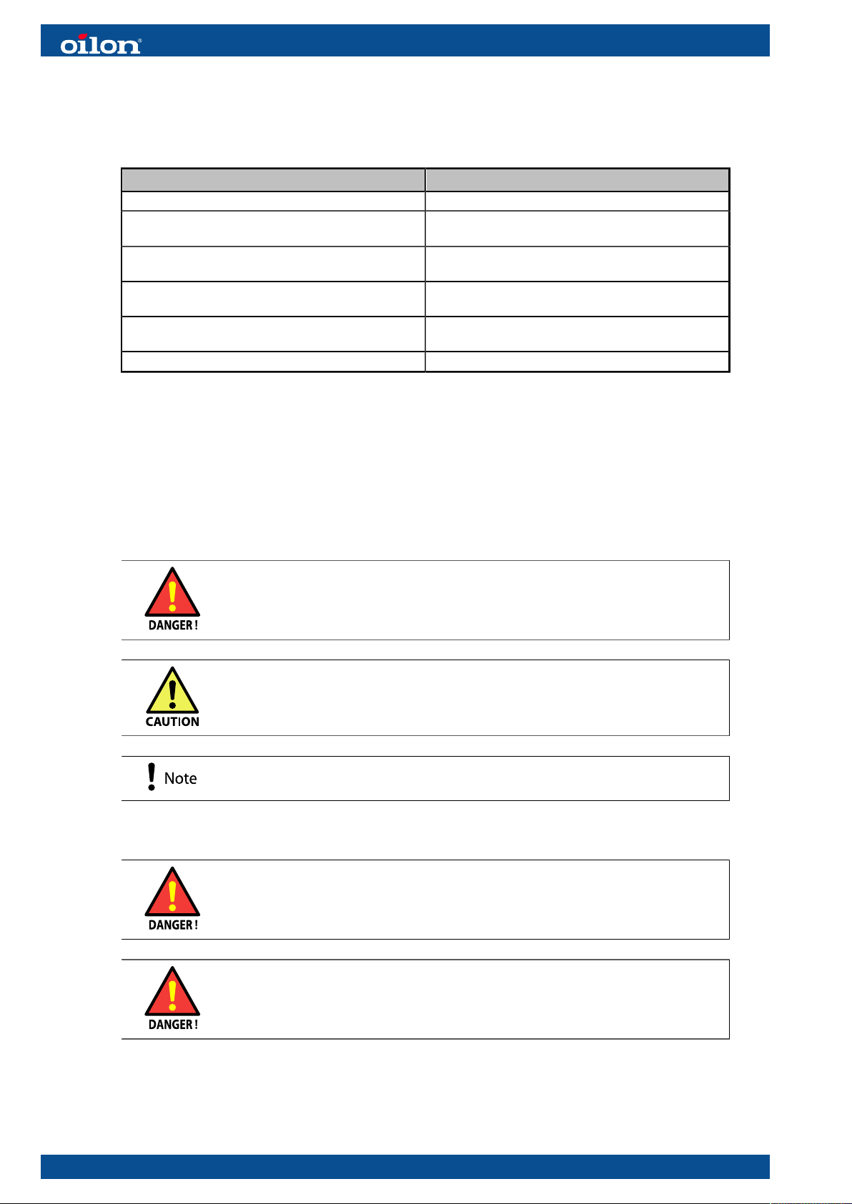
1.3 Instructions and diagrams
Document Designation
Installation and operation manual M8009
RE 05 28–33
Electric diagram
110415
RE 05 38–48
Electric diagram
110414
RE 05 56–66
Electric diagram
110412
RE 05 76–96
Electric diagram
110413
Quick guide 34793587
1.4 Safety notice and warnings
Read these instructions carefully before installation, commissioning, operation, or
maintenance of the device. The given instructions must be followed. Throughout this
manual, the following three symbols are used to point out very important information:
Be careful. The DANGER symbol indicates a possible danger of bodily
harm or lethal injury.
Pay attention. The CAUTION sign indicates a possible danger of
damage to the device, components or surroundings.
Note indicates tips, hints, and other essential information.
Keep these instructions as well as the electrical diagrams available near the device.
Installation, commissioning, or service of the appliance is to be carried
out by authorized and trained personnel only, adhering to all local
regulations and requirements.
Wear proper hearing protection and personal protective equipment,
such as protective footwear, gloves, and safety goggles when
necessary.
4 (74) M8009 2147EN

Electrical safety
Once powered on, some of the unit’s components carry a hazardous
voltage. Always pay attention to electrical safety when working with or
near electrical components.
Before any maintenance or servicing, switch off electricity using the
main switch and ensure that there is no voltage present in the unit’s
components.
Refrigerant
Refrigerant leaking from an open or broken circuit may cause
asphyxiation, severe frost damage, arrhythmia, or neurological
symptoms. If you suspect a refrigerant leak, leave the area immediately,
and seek fresh air. Help and warn others.
Safety devices
Do not bypass, disable, or damage any of the unit’s pressure switches
or other safeguards with tools, by accessing the system’s software, or
by any other means.
Bypassing the unit’s safeguards may lead to equipment failure, damage to property or
injury to people.
Lifting and handling
The weight of the unit presents a crush hazard. Use safe work methods
when lifting and handling the unit.
During lifting, do not walk or work under the heat pump or any other
suspended load.
Other considerations
To avoid slipping, keep floor surfaces dry, and seal off or report any
leaks that you detect.
M8009 2147EN 5 (74)

1.5 Transportation and storage
Storage
Store the unit upright in a warm, dry place. Protect the device against water and dust.
Do not stack goods on the unit.
Transportation
Transport the unit upright and protected against water and dust. Do not stack goods
on the unit. Use only safe lifting and handling methods when moving or lifting the
unit. After lifting, lower the unit carefully down onto the floor. Hard impacts can cause
equipment damage.
Do not tilt the unit.
● If the unit is tilted beyond 45 degrees, the compressor may not receive proper
lubrication at startup. As a result, the compressor may become damaged.
● If the unit has been accidentally tilted beyond 45 degrees, leave the unit in vertical
position for at least three hours before starting the compressor.
Lifting
Lift and move the unit with a hand pallet truck or forklift.
● Lift and move the unit only so that both forks of the lifting device extend under the
whole unit.
● Keep the exterior panels of the compressor unit closed when lifting and moving the
heat pump.
● Do not lift the unit from under the control cabinet.
● Do not use the user interfaces as support points when lifting the unit.
Two-unit heat pumps:
Lift the tower consisting of two units only from below the lower unit.
6 (74) M8009 2147EN

1.6 Scope of delivery
Equipment and components
Item PCS Designation
Outdoor temperature sensor 1 36217226
Outdoor temperature sensor ver. 1
Delivered with a solar screen panel.
NTC 1 k.
Condenser pump, RE 05 28–48 1 34023075 Wilo-Stratos PARA 25/1-12 T16180 mm 6h
Condenser pumps, RE 05 56–96 2 34023075 Wilo-Stratos PARA 25/1-12 T16180 mm 6h
Buffer tank temperature 1
DHW storage tank temperature 1
Heating circuit 1 flow temperature 1
Connected to the heat pump’s control cabinet,
cable length approximately 4 m.
Sensors and actuators
Controller Piping
diagram
pos.
BRINE CIRCUIT
B91 TE101 Brine circuit in (evaporator in) S
B92 TE102 Brine circuit out (evaporator out) S
Q8 P101 Brine pump (evaporator circuit pump) O
HEATING
B71 TE201 Heating water return (condenser in) S
B21 TE202 Heating water flow (condenser out) S
Q9 P201 Heating pump (condenser circuit pump) S
K25/K26 EB203 In-line heater, condenser circuit -
B4 TE255 Buffer tank temperature (tank upper section)* S
B41 TE256 Buffer tank temperature (tank upper lower section) O
B3 TE265 DHW storage tank temperature (tank upper section)* S
B31 (B3) TE266 DHW storage tank temperature (tank lower section) O
Q8 FV202 Change-over valve O
B9 TE0 Outdoor temperature S
HEATING CIRCUIT 1
B1 TE212 Heating circuit 1 flow temperature* S
Q2 P221 Heating circuit 1 pump O
Y1/Y2 FV222 Heating circuit 1 control valve O
B5/HMI1 TE213 Room temperature 1 O
HEATING CIRCUIT 2
B12 TE222 Heating circuit 2 flow temperature OA
Q6 P221 Heating circuit 2 pump OA
Y5/Y6 FV222 Heating circuit 2 control valve OA
B52/HMI2 TE223 Room temperature 2 O
M8009 2147EN 7 (74)

Controller Piping
diagram
pos.
HEATING CIRCUIT 3
B14 TE232 Heating circuit 3 flow temperature OA
Q20 P231 Heating circuit 3 pump OA
Y11/Y12 FV232 Heating circuit 3 control valve OA
B53/HMI3 TE233 Room temperature 3 O
REFRIGERANT CIRCUIT
K1 COMP1 Compressor S
B81 TE2 Hot gas temperature S
E9 PS1 Low pressure switch S
E10 PS2 High pressure switch S
CONNECTION DEVICE
OZW/
OCI672
O
S: Standard equipment
O: Optional accessory, can be connected to the heat pump’s automation system and enabled without
additional equipment.
OA: Optional equipment that requires an auxiliary controller kit (controller + enclosure) for installation.
1.7 Accessories
For a full list of available accessories, please refer to brochures and price lists. Storage
tanks are presented in a separate storage tank brochure.
Accessories
Accessory Temperature sensor NTC10k 5 m
Designation 36217266
Description Sensor with flexible cable (length: 5 m), metallic probe (diameter: 6 mm, length: 50
mm), 1xNTC 10 kOhm, 2 wires, B(25/85)=3976, t0.97 s
Intended use Buffer tank temperature TE255
Heating circuit flow temperature TE212, TE222, TE232
Accessory Sensor pocket 6x200 G1/2
Designation 34021268
Description For 6 mm sensor probes, with cable gland, depth: 200 mm, G1/2" outer thread,
brass
Intended use Sensor pocket for buffer tanks and heating circuits
Compatible
equipment
36217266
Accessory Remote connection device
OCI670/109
Designation 36108276
Description Siemens OCI670/109. For remote connection through the Climatix IC cloud service.
Local connection through a USB cable. Connects to the heat pump controller
through an LPB bus (DB+/MB–) and to the internet through a network cable. You
can establish the connection with an internet browser, the Siemens ACS790
computer program or the Siemens Climatix IC mobile app.
8 (74) M8009 2147EN
Ce manuel convient aux modèles suivants
21
Table des matières
Autres manuels Oilon Brûleur

Oilon
Oilon GP-6.10 P Manuel d'utilisation

Oilon
Oilon RP-150 T Manuel utilisateur

Oilon
Oilon GP-600 M Manuel utilisateur

Oilon
Oilon KP-6 Manuel

Oilon
Oilon Junior Pro 1 J10 Manuel

Oilon
Oilon GKP-350 M Manuel utilisateur

Oilon
Oilon GKP-50 MH Manuel utilisateur

Oilon
Oilon GP-350 Manuel utilisateur

Oilon
Oilon KP-6 Manuel utilisateur

Oilon
Oilon RP-130 H Manuel utilisateur


