Northern Lights GEM Series Manuel utilisateur

www.northern-lights.com
M864W3
GEM Series Sound Enclosure
Assembly Instructions
06-78700 M864W3 GEM COVER PAGE

Corporate Headquarters
4420 14th Avenue NW
Seattle, WA 98107
Tel: (206) 789-3880
Fax: (206) 782-5455
Southeastern U.S.A.
1419 W Newport Center Dr
Deereld Beach, FL 33442
Tel: (954) 421-1717
Fax: (954) 421-1712
Alaska Branch Ofce
1200 West International
Airport Road
Anchorage, AK 99519
Tel: (907) 562-2222
Fax: (907) 563-1921
East Coast Branch
15 Aegean Dr.
Suite 4
Methuen MA 01844
Tel: (978) 475-7400
Fax: (978) 475-7745
Gulf Branch
19 Veterans Memorial Blvd.
Kenner, LA 70062
Tel: (504) 360-2180
Toll Free: (800) 843-6140
Northern Lights
4420 14th Avenue NW
Seattle, WA 98107
Tel: (206) 789-3880
Fax: (206) 782-5455
Copyright ©2020 Northern Lights, Inc.
All rights reserved. Northern Lights™, and
the Northern Lights logo are trademarks of
Northern Lights, Inc.
Printed in U.S.A.
LIT NO.: L817 7/19

M864W3 GEM Sound Enclosure
1
SPECIFICATIONS
Enclosure (installed on generator base):
Length (OA) 48.9 in (1243 mm)
Width 25.0 in (635 mm)
Height 28.1 in (713 mm)
Assembled weight - shield only: 55.0 lbs (24.9 kg)
Assembled weight w/ genset: 952.2 lbs (432 kg)
ITEM # DESCRIPTION NLI P/N QTY NOTES
1. Rear panel assembly 06-78703 1
2. M8atwasher 15-11000 4 loose,bagged
3. M8 lock washer 15-00705 4 loose, bagged
4. M8 hex head capscrew 12-00776 4 loose, bagged
5.
Service side bottom valence assembly
06-78707 1
6.
Non-service side bottom valence assembly
06-78709 1
7. Front bottom valence assembly 06-78719 1
8. Non-service side panel assembly 06-78715 1
9. Service side panel aft assembly 06-78713 1
10. Front panel assembly 06-78701 1
11. Seal bar assembly 06-78723 1
12. Top panel assembly 06-78705 1
13. Service side panel, fwd assembly 06-78711 1
14. Grommet 1-1/8” x 1-7/8” OD 00-70146 2 loose, bagged
15. Leak detection alarm light assembly 22-90382 1 loose, bagged
16. E-stop/leak alarm harness 22-72024 1 loose, bagged

Prior to assembly, inspect all components for damage. Report any damage to the shipping company. Check the packing list in the back of this manual
to be sure all parts are included.
Select a mounting location in accordance with the guidelines in the IM1000 Installation Manual. The generator set must typically be mounted on a
rigid,atsurfaceaboveastrongstructure,suchasthevessel’sstringers,tominimizevibrationtransferencetothehull.
Note that the generator set is designed for single side service. When viewed from the rear, the right hand side is the service side and should be
exposed for easy maintenance access.
Installthegeneratorsetinthevesselasneartoalevelattitudeaspossible.Ensurethattheenclosure’srighthandsideandrearareatthe
recommendeddistances(6inchrecommended,4inchminimum.)fromthevessel’sbulkheads.
Note: The Generator set may still possess original factory lifting points. These lifting points will need to be loosened and rotated down, below the highest
point of the engine. Be sure to tighten these bolts before installing generator set.
AVOID POSITIONING THE ENCLOSURE INTO CORNERS WITH OVERHEAD BLOCKED TO REDUCE CHANCE OF INTAKE/EXHAUST AIR
RECIRCULATION OUTSIDE THE SHIELD.
2

A
06-78700 M864W3 GEM Bottom of page 2.
2.
A
B
STEP 1.
INSTALL REARPANEL ASSEMBLY (ITEM #1)
TO THE BACK FACE OF THE GENSET BASE.
ALIGN SLOTS IN TAB TO BASE FRAME HOLES.
SECURE WITH HARDWARE, ITEMS 2,3, AND 4.
DETAIL B
STEP 2.
WHEN THE REAR PANEL ASSEMBLY IS SECURED, INSERT
GENSET AIR INTAKE SNORKEL HOSE INTO THE RECIEVER
AS SHOWN. PUSH INTO HOLE FIRMLY BUT DO NOT FORCE
HOSE ALL THE WAY IN. THERE IS A TAB STOP THAT LIMITS THE
HOSE INSERTION. PUSHING THE HOSE TOO FAR INSIDE THE
RECIEVER WILL CAUSE INTAKE AIR BLOCKAGE AND POOR
ENGINE PERFOMANCE.
DETAIL A
M8 HEX HEAD CAPSCREW (ITEM #4 )
M8 LOCK WASHER (ITEM #3)
M8 FLAT WASHER (ITEM #2)
3

B
C
STEP 4.
INSTALL LEFT SIDE LOWER VALENCE (ITEM#6).
NOTE THERE ARE TWO CAPTIVE NUTS FEATURED
ON THE HORIZONTAL FLANGE OF THIS PART.
STEP 3.
INSTALL RIGHT SIDE LOWER VALENCE PANEL (ITEM#5).
NOTE THIS PART HAS TWO CLIP ON NUTS IN VERTICAL
FLANGE.
DETAIL C
NOTE PRE-INSTALLED PINS.
GUIDE THESE INTO CORRESPONDING HOLES
IN REAR PANEL/FRONT LOWER VALENCE
PANEL. PUSH FIRMLY TO SNAP INTO PLACE.
DISPLACED PINS MAY BE RE-SEATED USING
A LONG TOOL SUCH AS A SCREW DRIVER OR
PRY BAR FROM THE INSIDE.
MOVE SOUND FOAM OUT OF THE WAY FOR
ACCESS TO PINS.
D
STEP 5.
INSTALL FRONT LOWER VALENCE (ITEM#7).
ALIGN CORRESPONDING HOLES TO PINS ON
BOTH LOWER SIDE VALENCE PANELS.
PUSH FIRMLY UNTIL IT SNAPS.
DISPLACED PINS MAY BE RESEATED AS
DESCRIBED IN DETAIL "C".
DETAIL D
STEP 6.
SECURE FRONT VALENCE TO BASE FRAME WITH
TWO EA: M8 FLATWASHER, LOCKWASHER, AND
HEX HEAD CAPSCREW (ITEMS 2,3,4).
06-78700 M864W3 GEM Page 3.
B
3.
B
4

C
5
A
E
B
D
F
C
G
REAR PANEL
06-78700 M864W3 GEM Page 4 upper.
4.
STEP 7.
CONNECT YOUR GENERATOR TO THE VESSEL.
C
a. Connect the exhaust elbow of the diesel engine to the exhaust system of the vessel. Pass the three inch exhaust hose through the opening provided in the
left side of the rear panel.
b.Connecttheseawaterpumptothevessel’swaterinlet.Passa3/4”IDhosefromthevessel’sseawaterstrainer,throughthebottomholeontheleftside
oftherearpaneltotheseawaterpumpinlettting.
c.Connectthevessel’sfuelsupplyandfuelreturntothegeneratorsetusingCoastGuardapprovedrubberfuelhose.Fuelconnectionsare5/16-37TJICinlet
and1/4-37TJICoutletlocatedatthefuelmanifoldonthebaseframeofthegeneratorset’srighthandside,throughthebottomholeintherightsideofthe
rear panel.
d.ConnecttheDCcontrolpanelharnesstothegensetengineharnessplugthroughthemiddleholeontherearpanel’srightmidside.
e. Connect the 12 volt battery leads to the generator set using the top hole on the left side of the rear panel.
f.ConnecttheACoutputleadsfromthegeneratorjunctionboxtothevessel’spowerdistributionpanel.Passthetwoleadsthroughthelowerholeontheright
side of the panel.
g. *OPTIONAL* These ports are used for siphon break applications.
Install connections for exhaust, AC power
leads, DC control panel leads, battery and
water inlet through holes in the rear panel
as shown in the drawing and as described
below:
STEP 7.
CONNECT YOUR GENERATOR TO
THE VESSEL

E
06-78700 M864W3 GEM Page 5.
D
STEP 8.
INSTALL NON-SERVICE SIDE PANEL (ITEM#8).
DETAIL E
SHOWING HOW THUMB SCREW
"B" ENGAGES LOWER CAPTIVE NUT.
F
G
THUMB SCREW A
THUMB SCREW B
THUMB SCREW B
DETAIL F
THUMB SCREW "B"
DETAIL G
THUMB SCREW A
5.
PANEL ATTACHES TO REAR PANEL AND LOWER VALENCE
WITH THUMB SCREWS "A" AND "B".
WITH PANEL IN PLACE USE THUMB SCREW "A" TO RETAIN
SIDE PANEL, MOVING ON TO THUMB SCREWS "B".
APPLY DOWNWARD PRESSURE AS YOU TURN THUMB SCREW "B"
TO ENGAGE THE CAPTIVE NUTS INSIDE THE LOWER VALENCE.
DO THE OPPOSITE TO REMOVE.
D
6

7
H
ITEM#10
DETAIL H
THUMB SCREW A
I
DETAIL I
THUMB SCREW A
LOCATOR PINS
06-78700 M864W3 GEM Page 6.
E
6.
STEP 9.
INSTALL FRONT PANEL ASSEMBLY (ITEM#10)
POSITION FRONT PANEL ON TOP OF THE FRONT LOWER VALENCE.
NOTE THE PINS IN THE BOTTOM OF THE FRONT PANEL ALIGN
TO HOLES IN THE LOWER VALENCE. ENGAGE, AND SECURE
TO THE SIDE PANEL WITH THUMB SCREW 'A' (DETAIL H) AND
THUMB SCREW 'A' IN BOTTOM FLANGE INSIDE THE FRONT
PANEL (DETAIL I) .
E
F
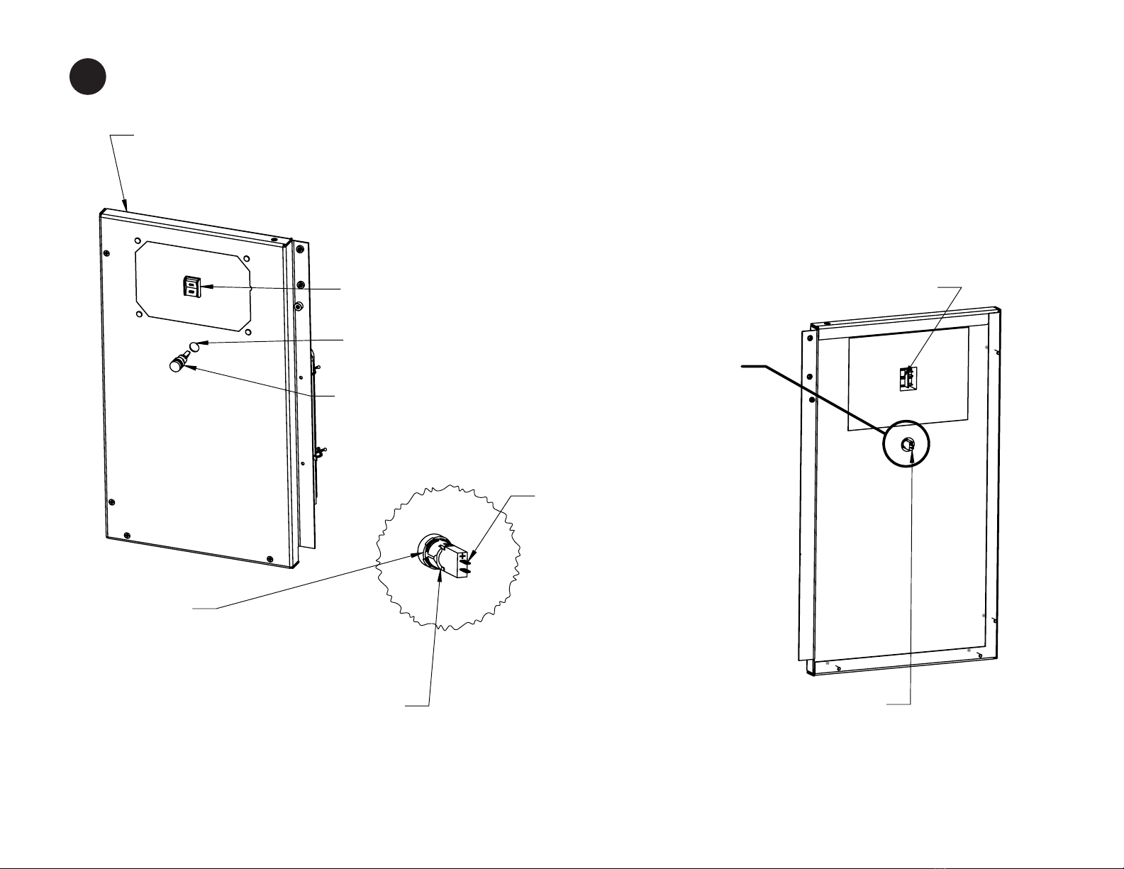
PRE-INSTALLED EMERGENCY STOP SWITCH
ITEM #9.
LEAK ALARM LIGHT MOUNTING HOLE
LEAK ALARM LIGHT ASSEMBLY (ITEM#15)
J
EMERGENCY STOP TERMINALS
HARNESS MOUNTING POINT
HARNESS MOUNTING POINT
LEAK ALARM LIGHT TERMINALS
DETAIL J
SCREW COLLAR
ITEM#15.
SOUND FOAM OMITTED
FOR VIEW CLARITY.
NOTE POSITIVE TERMINAL
POLARITY, POSITION AT
TOP.
06-78700 M864W3 GEM Page 7
F
STEP 10
PRIOR TO INSTALLING THE SERVICE SIDE AFT PANEL (ITEM#9) THE LEAK ALARM LIGHT AND CONNECTING
HARNESS (ITEM#16) MUST BE INSTALLED. START WITH THE ALARM LIGHT, THEN FOLLOW WITH THE HARNESS
AS SHOWN IN THE FOLLOWING ILLUSTRATIONS.
7.
UNSCREW COLLAR RING FROM LIGHT
ASSEMBLY TO INSTALL THROUGH PANEL.
RE-INSTALL COLLAR TO SECURE.
8
Autres manuels pour GEM Series
3
Ce manuel convient aux modèles suivants
1
Table des matières
Autres manuels Northern Lights Enceinte


 Manuel utilisateur")


