Terminal
number
Terminal
number
DRB-2-2-00 SIN
1➔2
2➔1
3➔3
4➔5
5➔6
6➔4
gure 3
1 2 354 6
BOITIER RAIL DIN
POUR MODULE CONNECTÉ
DIN RAIL BOX
FOR RELAY SWITCH
Référence : DRB-2-2-00 • Intensité maximum : se reporter à la notice
du module raccordé • Rail DIN compatible : Type Ω EN 50022
Modules compatibles : SIN-X-1-XX, SIN-X-2-XX, SIN-X-RS-XX, SIN-X-FP-XX
Température de fonctionnement : -20°C à 40°C
Dimensions : 87x27x58 mm • Poids : 5g • Garantie : 2 ans
Reference: DRB-2-2-00 • Maximum intensity: please refer to the user guide of the
connected relay switch • Compatible DIN Rail: Type Ω EN 50022
Compatible relay switches: SIN-X-1-XX, SIN-X-2-XX, SIN-X-RS-XX, SIN-X-FP-XX
Operational temperature: -20°C to 40°C
Dimension: 87x27x58 mm • Weight: 5g • Warranty: 2 years
DANGER D’ÉLECTROCUTION DANGER OF ELECTROCUTION
AVANT TOUTE INSTALLATION ASSUREZ-VOUS D’AVOIR COUPÉ L’ALIMENTATION
ÉLECTRIQUE SOUS PEINE D’ÉLECTROCUTION.
Coupez directement l’alimentation depuis le coffret électrique, pour éviter tout risque d’électrocution. Ce boitier
Rail DIN est conçu pour une utilisation sous tension, une mauvaise installation peut entraîner un incendie ou un
choc électrique. Le boitier Rail DIN doit obligatoirement être installé ET connecté en suivant scrupuleusement
les instructions de cette notice. NodOn® ne pourra être tenu responsable en cas d’accident ou de dommages
dus au non-respect des instructions de montage. Coupez l’alimentation avant toute intervention et n’effectuez
aucune modification si la LED du module situé dans le boitier Rail DIN est allumée.
BEFORE ANY INSTALLATION MAKE SURE THE POWER SUPPLY IS DISCONNECTED
TO AVOID ANY RISK OF ELECTROCUTION.
Directly cut the power supply from the breaker box to avoid any risk of electrocution. This DIN Rail
Box is designed to be used power up, a wrong installation can create a re or an electric shock. The
DIN Rail Box must be installed and connected carefully following the instructions of this user guide.
NodOn®will not be responsible for any loss or damage resulting from a non-respect of the instructions
of this user guide. Cut the power supply before any operation and don’t do any modication if the relay
switch LED located into the Rail DIN Box is ON.
INSTALLATION INSTALLATION
• N’utilisez jamais l’appareil s’il n’est pas correctement
installé et placé à l’intérieur d’un tableau électrique
conforme aux normes en vigueur.
• Tenez le produit éloigné de tous liquides.
• Never use the device if it is not correctly
installed and placed inside an electrical panel in
conformity with the current standards.
• Keep the product far away from liquids.
www.nodon.fr section “support”
For user guides in other
languages, please visit
www.nodon.fr/notices
www.nodon.fr section “support”
For user guides in other
languages, please visit
www.nodon.fr/notices
PRÉCAUTIONS D’USAGES USE CAUTIONS
SAV SAV
MODE D’EMPLOIFR User guide
EN
Procédure d’installation
Coupez l’alimentation générale du tableau
électrique.
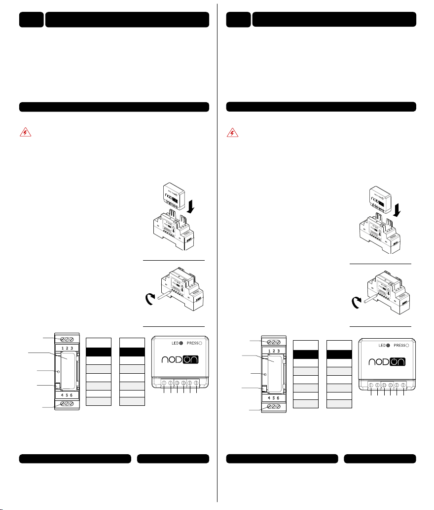
Dévissez les bornes du module que vous
souhaitez raccorder.
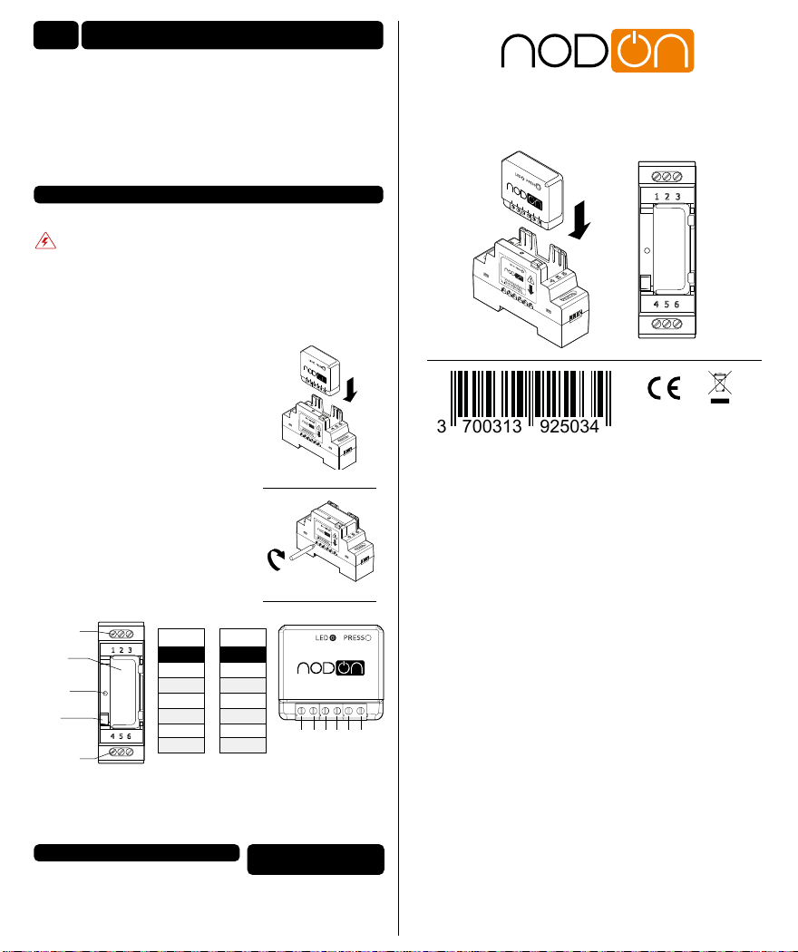
Insérez le module dans le Boîtier Rail DIN
en respectant le sens d’introduction du module,
le bornier doit se situer à gauche (voir gure 1).
Vériez que les bornes sont bien dévissées et
veillez à ne pas plier les broches situées
à l’intérieur du boitier.
Vissez les 6 vis du module an de xer
les deux éléments entre eux (voir gure 2).
An de faciliter le raccordement, dévissez les 6
vis du bornier de connexion du Boîtier Rail DIN.
Installez le boitier comprenant le module
sur le Rail DIN du tableau électrique.
Raccordez les bornes en fonction de votre
module suivant le schéma (voir gure 3).
gure 2
Module
SIN Relay
switch
Bouton Button
Guide
lumière Light guide
Bornier de
connexion
Bornier de
connexion Terminals
Terminals
Remettez l’alimentation générale en marche et vériez que la LED du module
s’allume à travers le guide lumineux.
Pour l’appairage ou la conguration de votre module, référez vous directement
à sa notice.
gure 1
Installation procedure
Cut the power supply of the electrical panel.
Unscrew the relay switch terminals you want
to connect.
Insert the relay switch on the DIN Rail Box
while respecting the direction of insertion of the
relay switch, the terminal block must be located
on the left (see gure 1).
Make sure the terminals are well unscrewed and
take care to not fold the pins located inside the
DIN Rail Box.
Screw the 6 screws of the relay switch to x
both elements together (see gure 2).
To facilitate the connection, unscrew
the 6 screws of the DIN Rail Box terminals.
Install the box with the relay switch on
the DIN Rail Box of the electrical panel.
Connect the terminals according to your
module according to the diagram (see gure 3). gure 2
Turn the power supply back on and check that the LED on the module lights up
through the light guide.
For the pairing or conguration of your module, please refer directly to its user
guide.
gure 1
Numéro de
borne
Numéro de
borne
DRB-2-2-00 SIN
1➔2
2➔1
3➔3
4➔5
5➔6
6➔4
gure 3
1 2 354 6