Newport 1601 Manuel utilisateur

Models 1601 and 1611
User’s Manual
High-Speed
Photoreceivers
These photoreceivers are sensitive to electrostatic
discharges and could be permanently damaged if
subjected even to small discharges. Ground your-
self adequately prior to handling these detectors or
making connections. A ground strap provides the
most effective grounding and minimizes the
likelihood of electrostatic damage
phone: (877) 835-9620
e-mail: tech@newport.com • www.newport.com

Contents 2
4
5
9
11
Warranty
Newport Corporation guarantees its
products to be free of defects for one year
from the date of shipment. This is in lieu of
all other guarantees, expressed or implied,
and does not cover incidental or
consequential loss.
Information in this document is subject to
change without notice. Copyright
2022-2012, 2001-1998, Newport
Corporation. All rights reserved.
Warranty
Introduction
Theory
Operation
Specifications
90099909 Rev. A
2

3
This Page intentionally left blank.

4
Introduction
The Newport Models 1601 1 GHz and 1611
850 MHz, low-noise photoreceivers address
the needs of the photodetector community in
the area of low-noise, high-gain, RF
photoreception. These photore-ceivers are
AC coupled and are capable of driving up to 1
V peak to peak into a 50-Ω load, with a
current gain of 700 V/A.
The performance of these units is achieved
through the use of solid RF design together
with the implementation of some of the latest
advances in commercially available amplifier
chips. The detector is shielded to avoid RF
pickup. New Focus offers two models to
match your different wave-length
requirements.
These photoreceivers have very large gain×
band-width products, low noise performance,
high drive capability and a large dynamic
range. They will enable wide bandwidth low-
noise detection of sig-nals distributed over
fiber-optic cables or found in high resolution
spectroscopy, fiber-optic sensors, optical
metrology, and many other applications.

5
Theory
The Model 1601 photoreceiver consists of a
silicon PIN photodiode followed by a low-
noise amplifier. The Model 1611 photoreceiver
consists of an InGaAs PIN photodiode with the
same amplifier.
The 1601 photodetector has a maximum
current of 5 mA and the 1611 photodetector
has a maximum current of 10 mA. Therefore,
the maximum input optical power is 10 mW for
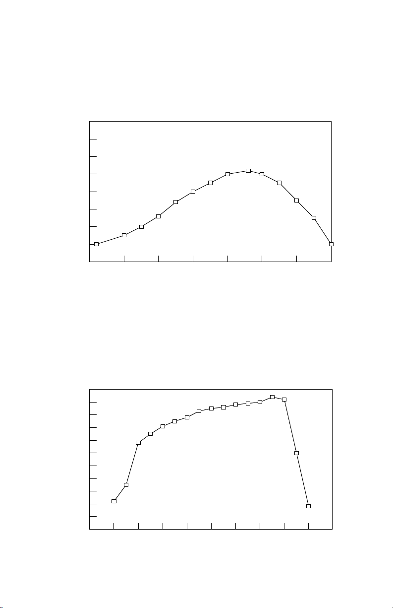
both detectors. The responsivity of the
photodiode is shown in Figs. 2a and 2b. Power
is delivered through a connector on the back
of the unit, and the entire package is shielded
to eliminate RF pickup. Typical frequency
responses for the Models 1601 and 1611 are
shown in Figs. 3a and 3b.
The amplifier is a low-noise, silicon amplifier
having a voltage gain of 15 and an input
impedance of 50 Ω. This unit can be
cascaded with other 50-Ω amplifiers.
Transmission lines connect the photodiode to
the amplifier and the amplifier to the output.
Microstrip transmission lines are used to
preserve speed and eliminate parasitic
inductance and capacitance that can cause
ringing. Rise time of the diode/amplifier
combination is less than 400 ps.
The AC-coupled 1601 and 1611 incorporate
blocking capacitors and a DC bias monitor
circuit as shown in Fig. 1. The corner frequency
of the high-pass filter on the AC-coupled
output is approx. 30 kHz; the corner frequency
of the low-pass filter on the DC bias monitor
output is approx. 20 kHz. The DC bias monitor
gain is 10 V/mA.

6
Transmission Line Transmission Line
G(f)
AC-coupled
Output
Optical Input
I-V
Transimpedance
Amplifier
(low-speed)
DC Bias
Monitor
Output
Vb
+
-
10k Ω
Fig. 1
Functional block diagram of
the Models 1601 and 1611.
7
Fig. 2a
Responsivity of the photodiode
used in the Model 1601.
300 400 500 600 700 800 900 1000
0.00
0.10
0.20
0.30
0.40
0.50
0.60
0.70
0.80
Wavelength, nm
Responsivity, A/W
Fig. 2b
Responsivity of the photodiode
used in the Model 1611.
800 900 1000 1100 1200 1300 1400 1500 1600 1700 1800
0.00
0.10
0.20
0.30
0.40
0.50
0.60
0.70
0.80
0.90
1.00
1.10
Wavelength, nm
Responsivity, A/W

8
Fig. 3a
Typical frequency response
of the Model 1601.
1 200 400 600 800 1000 1200
-10.0
-8.0
-6.0
-4.0
-2.0
0.0
2.0
4.0
Frequency, MHz
Response, dB
Fig. 3b
Typical frequency response
of the Model 1611.
0200 400 600 800 1000 1200
-10.0
-5.0
0.0
Frequency, MHz
Response, dB

9
Operation
To obtain optical input:
1. Plug one end of the power cable on to the
connector on the back of the module and the
other end into a ±15-V power supply. (We
recommend the Newport Model 0901 power
supply.) Turn on the supply.
Two different power cables have been shipped
with your detector: a Newport Model 0924
banana plug-to-pico (m8) cable and a Model 0923
pico (m8) double ended cable. If you have a
Newport Model 0901 power supply, use the
Model 0923 cable on one of the supply’s 0.3-A
microconnector outputs. Use the Model 0924
cable with a power supply other than the 0901
providing a minimum of 0.25 A of current on ±15
V. The convention of the three banana plugs is:
Banana Plug Voltage
Red +15 V
Green COM/GND
Black -15 V
2.Turn on the optical beam.
3.For direct optical beam input, align the module
in front of the optical beam.
For fiber-optic cable input, connect the fiber
optic input cable from your optical source to
the FC-input connector port on the front of the
module.

10
Note: To operate the receiver in the linear
region, keep the input power levels below the
Input Power specification on pages 11 and 12.
(The Input Power is wavelength dependent
and is inversely proportional to the
responsivity.)
To set up the output connection:
1.If your RF measurement instrument has a
male connector, connect it directly to the
SMA female output connector (labeled
“AC”) on the back of the module or connect
with the appropriate cable.
If your instrument has a female connector,
con-nect with the appropriate cable.
2.Monitor the DC bias on the output labeled
“DC” with the provided SMB-to-BNC cable.
Ce manuel convient aux modèles suivants
1
Autres manuels Newport Récepteur

Newport
Newport 2151 Manuel utilisateur

Newport
Newport zW Series Manuel utilisateur

Newport
Newport 2007 Manuel utilisateur

Newport
Newport 2107 Manuel utilisateur

Newport
Newport 1801 Manuel utilisateur

Newport
Newport 1580-A Manuel utilisateur

Newport
Newport 1607-AC Manuel utilisateur

Newport
Newport 2051 Manuel utilisateur

Newport
Newport NIRVANA Manuel utilisateur

Newport
Newport 1807 Manuel utilisateur


