Revision 1.0 Digital Lynx SX System Installation Guide
3/3/2011
Page 2
Table of Contents
1Document Overview................................................................................................... 3
2Electrostatic Sensitive Equipment .............................................................................. 3
3Revision History ......................................................................................................... 3
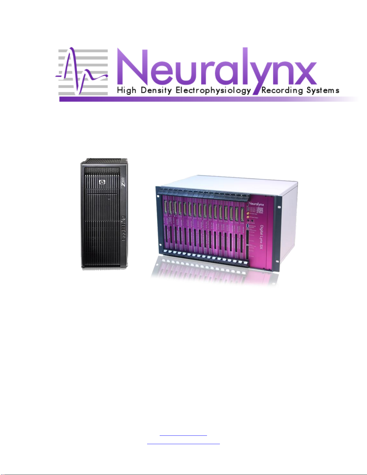
4Unpacking the Digital Lynx SX ................................................................................. 4
4.1 Turning on Cheetah.............................................................................................. 6
5Connecting the Ribbon Cables.................................................................................... 7
6Connecting the Headstage........................................................................................... 8
7Testing the System...................................................................................................... 9
7.1 PC Board Connections ....................................................................................... 10
8Normal Usage ........................................................................................................... 11
List of Figures and Tables
Figure 1 Power Indicator LED's ......................................................................................... 4
Figure 2 Fiber Optic Data Link to PC................................................................................. 5
Figure 3 Cheetah Welcome Screen..................................................................................... 6
Figure 4 –80 Pin Connector................................................................................................ 7
Figure 5 Digital Lynx SX ................................................................................................... 8
Figure 6 Tether Adapter Connection .................................................................................. 8
Figure 7 Test Mouse Setup................................................................................................ 9
Figure 7-8 Analog Signal Breakout.................................................................................. 10