network MOT-BOX Manuel utilisateur
MOT-BOX
Hard-shell case for one flashlink®2U frame
Product Manual
Rev. 0

MOT-BOX Rev. 0
Network Electronics ASA
Thorøya
P.O. Box 1020
Sandefjord, Norway
Phone: +47 33 48 99 99
Fax: +47 33 48 99 98
E-mail: [email protected]
www.network-electronics.com
Service Phone: +47 90 60 99 99
Revision history
Current revision of this document is the uppermost in the table below.
Revision Replaces Date Change description
0 A 13/07/05 No changes; first official release.
A - 09/06/05 NBS: Initial Revision.
2

MOT-BOX Rev. 0
Contents
Revision history............................................................................... 2
1 Product overview......................................................................... 4
1.1 Features:......................................................................................................4
2 Specifications .............................................................................. 5
2.1 General specifications ..................................................................................5
2.2 Front view ...................................................................................................5
2.3 Rear view.....................................................................................................5
3 Connections ................................................................................ 7
3.1 Service connections .....................................................................................7
3.2 Module connections....................................................................................8
3.2.1 MB-BP-01 8
3.2.2 MB-BP-02 9
3.2.3 MB-BP-03 9
3.2.4 MB-BP-04 10
3.2.5 MB-BP-05 10
3.2.6 MB-BP-06 11
3.2.7 MB-BP-07 11
3.2.8 MB-BP-08 12
3.2.9 MB-BP-09 12
3.3 MB-FR-1RU ................................................................................................13
3.4 Frame reconfiguration ...............................................................................14
4 MOT-BOX safety precautions..................................................... 15
5 Laser safety precautions ............................................................. 16
General environmental requirements for flashlink®equipment ...... 17
Certificate of Conformity .............................................................. 18
Product Warranty ......................................................................... 19
3

MOT-BOX Rev. 0
1Product overview
MOT-BOX is a lightweight mobile transport enclosure for the flashlink®range
of products.
MOT-BOX houses all flashlink®optical transport, signal processing and
distribution cards including WDM/CWDM. Its rugged design and connector
panel, including an expanded beam hermaphroditic fiber connector, makes it
the ideal choice for all mobile and outside broadcast applications.
Options include a fiber reel with MIL specified tactile fiber, AC and DC power
supplies, and a monitoring/alarming function via Network’s GYDA controller.
1.1 Features:
-Lightweight 3RU Mobile Transport Enclosure.
-Full set of flashlink optical, signal processing and distribution cards
including WDM/CWDM.
-Expanded beam hermaphroditic fiber connector.
-Fiber reel with MIL specified tactile fiber (option).
-AC and DC power supply option.
-Rugged connector panel and enclosure design for tough mobile use
(audio on XLR-breakouts).
-Monitoring/Alarming via GYDA controller (option).
4

MOT-BOX Rev. 0
2Specifications
2.1 General specifications
AC Power: PWR-AC15/15/5/5V
AC power supply module 100-260 VAC.
DC Power (optional): PWR-DC15/15/5/5V
DC power supply module 36-72 VDC.
Dimensions: WxDxH with front- and rear cover: 530 x 570 x 215 mm,
Without front- and rear cover: 530 x 425 x 215 mm.
Weight: Including PSU and 10 modules: <12 kg.
Card slots: 10.
Power Supply slots: 2.
Internal voltages: +5V, -5V, +15V, -15V.
2.2 Front view
The front view of the MOT-BOX (with front cover removed) shows the status
LEDs for each module that is included box + two green LEDs for the power
supply modules.
Figure 1: LEDs in front of the flashlink frame.
The uppermost LED of each module card is a "general status" LED.
-Green light means that the card is OK.
-Red light means that the card is faulty.
-No light means that the power is not switched on.
The meaning of each LED on the module cards is described in their respective
User Manuals.
2.3 Rear view
Figure 2 shows an example of a fully equipped MOT-BOX, seen from the rear
side (with rear cover removed).
To the left is the connector module for the power supply delivered with the
MOT-BOX. The other connector modules are described in Chapter 3.2.
5

MOT-BOX Rev. 0
Figure 2: Example of fully equipped MOT-BOX.
6

MOT-BOX Rev. 0
3Connections
3.1 Service connections
The figure below shows the power connections, Ethernet connections and the
expanded beam hermaphroditic fiber connector of the frame.
Figure 3: Connector module for the power supply.
AC: Connect with a mains cord with an IEC 320 connector to the MOT-BOX.
DC: Connect with a 4-pin XLR (female) from the external DC power supply to
the Neutrik NC4MD-L-1 4-pin XLR (male) receptacle of the MOT-BOX.
The following pin-out is applicable:
Pin #1 Negative part of 48VDC supply Input
Pin #2 Not in use
Pin #3 Not in use
Pin #4 Positive part of 48VDC supply Input
A green LED will light on the front when the power supply (AC or DC) is in
operation.
Ethernet: Connect with an RJ-45 plug to the Neutrik NE8FDV-YK receptacle of
the MOT-BOX.
Fiber: Connect your fiber cable with a Stratos HXMA 4-channel plug to the
Stratos HXMA 4-channel expanded beam hermaphroditic fiber receptable of
the MOT-BOX. You may connect the other end of the fiber cable to the
dedicated 1RU frame, MB-FR-1RU. See Chapter 3.3 for more information.
7
MOT-BOX Rev. 0
3.2 Module connections
The connector/receptacle layout on the rear of the MOT-BOX is depending on
the models that are included in the box/frame.
The following options are available:
Backplane Associated module(s)
MB-BP-00 Blindplate, no module associated.
MB-BP-01 ADC-AES
MB-BP-02 DAC-AES, DA-AA or DA-AES
MB-BP-03 SDI-OE, SDI-EO, HD-OE or HD-EO
MB-BP-04 DA-SDI, DA-SDI-NRC, DA-HDSDI, ADC-SDI, ADC-SDI-CC or DAC-SDI
MB-BP-05 AV-MUX
MB-BP-06 AAV-MUX or AVA-MUX
MB-BP-07 AV-DMUX, AAV-DMUX or AVA-DMUX
MB-BP-08 D422-MG (RS422)
MB-BP-09 D422-MD (GPI in and out)
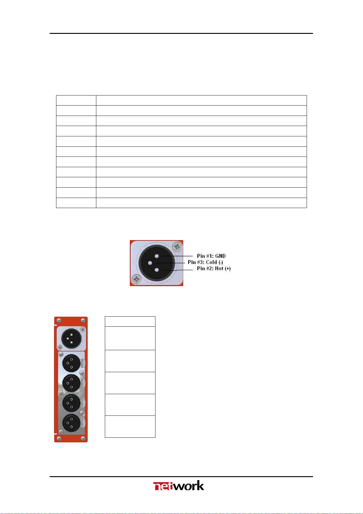
The pin-out of the XLR connectors in the following Chapters are according to
known standards, as follows:
Figure 4: XLR pin-out.
3.2.1 MB-BP-01
Figure 5: MB-BP-01.
ADC-AES
AES OUT
Audio IN 1L
Audio IN 1R
Not in use
AES11 Sync.
8

MOT-BOX Rev. 0
3.2.2 MB-BP-02
Figure 6: MB-BP-02.
DAC-AES DA-AES DA-AA
AES IN Audio IN
Audio OUT 1L AES OUT1 Audio OUT1
Audio OUT 1R AES OUT2 Audio OUT2
Audio OUT 1L AES OUT3 Audio OUT3
Audio OUT 1R AES OUT4 Audio OUT4
3.2.3 MB-BP-03
Figure 7: MB-BP-03.
SDI/HD-EO SDI/HD-OE
SDI/HD IN Not in use
SDI/HD OUT 1
SDI/HD OUT 2
9

MOT-BOX Rev. 0
3.2.4 MB-BP-04
Figure 8: MB-BP-04.
Video DA1ADC-SDI ADC-SDI-CC DAC-SDI
IN Ch1 CVBS/Y SDI IN
01 Ch2 R/Pr BBurst
02 Dup1 G/Y CVBS
03 Dup2 B/Pb/C R
04 SDI 1 SDI OUT G
05 SDI 2 SDI OUT B
06 SDI 3 SDI OUT SDI OUT
Not in use
3.2.5 MB-BP-05
Figure 9: MB-BP-05.
AV-MUX
SDI IN
SDI OUT
AES IN 1
AES IN 2
AES IN 3
AES IN 4
10
1DA-VA, DA-SDI, DA-SDI-NRC, DA-HDSDI
Table des matières


 Manuel utilisateur")


