NetWave NW6000-7001 Manuel utilisateur

NW6000-7001 QIG
-1- -2- -3-
1. Overview
NW6000-7001 DNV GL Managed Industrial Ethernet Switch is
designed for harsh environments to withstand vibration, shock,
free fall and power surges. The switch provides layer 2+ software
features required in marine systems and is DNV GL certied. It
includes 8-port 10/100Mbps RJ45 downlink, 2-port GbE SFP uplink
and supports Modbus TCP communication.
2. Package Checklist
Panel view
4. Grounding the switch
5.1 Wiring Power Input
5.1.1 The Switch with terminal block
You can use “PWR” for Primary Power input and “RPS” for Redundant
Power Input. Check the polarity while connecting.
Top view of Terminal Block is shown in the gure below:
Grounding and wire routing help limit the eects of noise due to
electromagnetic interference (EMI). Run the ground connection from
the ground screw to the grounding surface prior to connecting
devices.
!ATTENTION:
A corrosion-free mounting rail is advisable. When installing,
make sure to allow for enough space between devices to
properly install the cabling. And provide ample space for
air ow.
3. Mounting and Dismounting to DIN-Rail
!ATTENTION:
The Switch is an open type device and shall be DIN-Rail
mounted or wall mounted (optional) in cabinet or enclosure
and the ambient temperature should not exceed 70°C (75°C
is not certied by UL).
!ATTENTION:
This product is intended to be mounted to a well-grounded
mounting surface such as a metal panel.
!
Terminal Block
Caution:
• Use copper conductors only
• Wiring cable temperature should
support at least 105°C
• Tighten the wire to a torque value 5lb
• The wire gauge for the terminal block
should range between 12~24 AWG
To insert power wire and connect the specied voltage range at a
maximum of 1.5A DC power to the power terminal block, follow the
steps below:
1. Use a at-head screwdriver to loosen the wire-clamp screws
2. Insert the negative/positive DC wires into the PWR-/PWR+
terminals, respectively
3. Tighten the wire-clamp screws to prevent the wires from loosening.
!ATTENTION:
Please use a power supply from 12~60VDC, the device
power shall be supplied by SELV circuit.
!WARNING:
Safety measures should be taken before connecting the
power cable. Turn o the power before connecting
modules or wires. The correct power supply voltage is
listed on the product label. Check the voltage of your
Please read and follow these guidelines:
• Use separate paths to route wiring for power and devices. If
power wiring and device wiring paths must cross make sure the
wires are perpendicular at the intersection point.
NOTE: Do not run signal or communications wiring and power
wiring through the same wire conduit. To avoid interference,
wires with dierent signal characteristics should be routed
separately.
• You can use the type of signal transmitted through a wire to
determine which wires should be kept separate. The rule of
thumb is that wiring that shares similar electrical characteristics
can be bundled together
• You should separate input wiring from output wiring
• We advise that you label the wiring to all devices in the system
Mounting the switch
Place the switch on the DIN-Rail from above using the slot, push the
front of the switch toward the mounting surface until it snaps into
place with a click sound.
5. Wiring requirements
Dismounting the switch
Press the switch from top and pull out the lower edge of the switch
and then remove the switch from the DIN-Rail.
The switch is shipped with the following items*.
If any of these are missing or damaged, please contact your customer
service representative for assistance.
• The Switch x 1
• DIN-Rail kit x 1
• Console Cable x 1
• Quick Installation Guide x 1
power source to make sure that you are using the correct
voltage. DO NOT use a voltage greater than what is
specied on the product label. Calculate the maximum
possible current in each power wire and common wire.
Observe all electrical codes dictating the maximum
current allowable for each wire size. If current exceeds
the maximum rating, the wiring can overheat causing
serious damage to your equipment.
Mounting the Switch
Click
Removing the Switch
Front ViewTop View
DIP Switches
9 10
CONSOLE
1
3
5
7
2
4
6
8
Reset
PWR RPS
ALM
POST
SFP
SFP
100Mbps
(Green)
LNK/ACT
(Green)
LASER ON
SPD
ALM
P9
P10
A
B
1 PWR
RPS
P1
P2
P3
P4
P5
P6
P7
P8
P9
2
3
4
5
6
7
8
9
10
11
12 P10
12~60VDC
+
+
PWR
RPS
ALM
Grounding
Screw
Power Input
Terminal Block
OFF ON
OFF
100M
ON
1000M
A
B
1
2
3
4
5
6
7
8
9
10
11
12
-4- -5- -6- v1.0
M64-0001080-000
Connect one end of an Ethernet cable into the Ethernet port of the
switch and the other end to the attached networking device.
• Ports 1-8 supports 10/100/1000Mbps speed
• Ports 9-12 supports 100FX/Gigabit speed
• All the RJ45 ports on the switch support auto-negotiation and
auto MDI/MDI-X to eliminate the need for crossover cabling.
* Category 5e cable or above should be used.
5.3 Cabling RJ45
Load External
Power
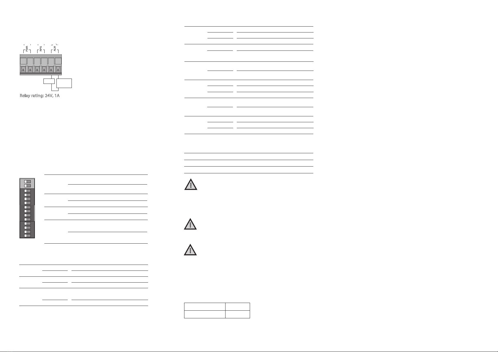
5.2 Wiring the relay contact (ALM)
The switch has one set of relay alarm
output. This relay contact uses two
contacts of the terminal block on the
switch top panel. The two contacts of
the terminal block connector are used
to detect user-congured events. The
two wires attached to the fault
contacts form an open circuit when a
user-congured event is triggered. If a
user-congured event does not occur,
the fault circuit remains closed.
Relay rating: 24V, 1A
6. DIP Switch Setting
Connect through Web Browser:
• Connect your computer to one of the Ethernet ports.
• Use the default IP-address 192.168.100.254 to login to the
switch.
9. Conguration
Default Username
Default Password
admin
netwave
NOTE: For more details on conguration please refer user manual.
8. Environmental limits
-40°C~75°C (-40°F~167°F)
-40°C~85°C (-40°F~185°F)
5 to 95% (non condensing)
Operating Temperature
Storage Temperature
Ambient relative humidity
!ATTENTION:
This device complies with Part 15 of the FCC rules.
Operation is subject to the following conditions:
1. This device may not cause harmful interference.
2. This device must accept any interference received
including interference that may cause undesired operation.
!ATTENTION:
If the equipment is used in a manner not specied by
Netwave, the protection provided by the equipment may
be impaired.
!ATTENTION:
Please leave at least 5cm of space at the left and right of
the unit for ventilation.
ON: Fiber port 1000Mbps support
OFF: Fiber port 100Mbps support
A
B
ON:
Primary power alarm reporting is enabled
OFF:
Primary power alarm reporting is enabled
1PWR
ON: Redundant power alarm reporting is enabled
OFF: Redundant power alarm reporting is disabled
2RPS
ON: Port 9~12 (SFP) link alarm reporting is
enabled per dip
OFF: Port 9~12 (SFP) link alarm reporting is
disabled per dip
3
~
12
P1
~
P10
P9
~
P10
A
B
OFF ON
1
2
ON
1
2
3
4
1
2
3
4
ON DIP
1
2
3
4
5
6
7
8
ON DIP
1
2
3
4
9
10
11
12
ON DIP
7. LED Indicators
Illuminated
O
PWR
(Green)
Primary power on
Primary power o or failure
Illuminated
O
RPS
(Green)
Redundant power on
Redundant power o or failure
Illuminated
O
ALM
(Red)
Alarm triggered for abnormal power status
and anomalous features.
Normal operation or DIP switch OFF
Illuminated
O
OFF LINE
(Red)
(9~10th
Fiber port)
No ber transceiver insertion
Fiber transceiver is ready on port
POST
(Green)
Switch is ready or running
Self-testing the device when power on
Switch is not ready
Illuminated
Blinking
O
SFP
(Green)
(9~10th
Fiber port)
Port link-up
Activity (receiving or transmitting data)
Port disconnected or link failed
Illuminated
Blinking
O
Illuminated
O
LASER ON
(Yellow)
Fiber transceiver is plugged into port 9 or 10
Both ber transceivers are not ready on
port 9 & 10
100
(Green)
(1~8th
RJ45 port)
Illuminated
O
Link speed at 100Mbps
Link speed at 10Mbps
LNK/ACT
(Green)
(1~8th
RJ45 port)
Port link-up
Activity (receiving or transmitting data)
Port disconnected or link failed
Illuminated
Blinking
O
Netwave Systems BV
Blauw-roodlaan 100, 2718 SJ Zoetermeer, The Netherlands.
+31 (0)6 215 021 67 (24/7)


