Ness 104-466 NIP300 Manuel utilisateur

REV1.5
Full HD Bullet IP Camera
104-466 NIP300
USER’S MANUAL
www.ness.com.au

COPYRIGHT NOTICE
All rights reserved. No part of this publication may be reproduced, transmitted or stored in a retrieval system in any form or by any means,
electronic, mechanical, photocopying, recording, or otherwise, without the prior written permission of Ness.
Ness reserves the right to make changes to features and specifications at any time without prior notification in the interest of ongoing
product development and improvement.
© 2012 Ness Corporation Pty Ltd ABN 28 069 984 372
HEAD OFFICE:
Ness Corporation Pty Ltd
ABN 28 069 984 372
Ph +61 2 8825 9222 Fax +61 2 9674 2520
SYDNEY
Ph 02 8825 9222 Fax 02 9674 2520
MELBOURNE
Ph 03 9875 6400 Fax 03 9875 6422
BRISBANE
Ph 07 3399 4910 Fax 07 3217 9711
PERTH
Ph 08 9328 2511 Fax 08 9227 7073
ADELAIDE
Ph 08 8152 0000 Fax 08 8152 0100
www.ness.com.au

1
Table of Contents
1. Overview ................................................................................................................................ 2
1.1 Features ...................................................................................................................... 2
1.2 Package Contents ....................................................................................................... 3
1.3 Dimensions .................................................................................................................. 4
1.4 Connectors .................................................................................................................. 5
2. Camera Cabling ..................................................................................................................... 7
2.1 Connect Power ............................................................................................................ 7
2.2 Connect Ethernet Cable............................................................................................... 7
2.3 Connect Alarm I/O ....................................................................................................... 7
3. Installation ............................................................................................................................. 8
3.1 Ceiling/Wall Mounting .................................................................................................. 8
3.2 Lens Adjustment (Vari-focal Lens only) ........................................................................ 9
4. System Requirements......................................................................................................... 10
5. Access Camera ................................................................................................................... 11
6. Setup Video Resolution ...................................................................................................... 15
7. Configuration Files Export/ Import .................................................................................... 16
Appendix A: Technical Specifications....................................................................................... 17
Appendix B: Delete the Existing DC Viewer .............................................................................. 21
Appendix C: Setup Internet Security ......................................................................................... 22
Appendix D: Video Resolution ................................................................................................... 23
2M- Quad Streams ................................................................................................................ 23
2M- Triple Streams................................................................................................................ 27
2M- Dual Streams ................................................................................................................. 29
2M- Single Stream ................................................................................................................ 29
2M Real time / 3M / 5M- Quad Streams ................................................................................ 30
2M Real time / 3M / 5M- Triple Streams ................................................................................ 35
2M Real time / 3M / 5M- Dual Streams .................................................................................. 38
2M Real time / 3M / 5M- Single Streams ............................................................................... 39

2
1. Overview
Supported with both H.264 and MJPEG standard, the product series not only
features in superior Full HD resolution for real-time streaming at 25/30 fps, but
also supplies D1 real-time streaming. With more computing power, the IP
Camera could provide more flexibility for users and system managers.
1.1 Features
Progressive Scan CMOS Sensor
Quad Streams support
Dual Streams, Full HD 1080P real-time + D1 real-time
Quad Streams Compression:
H.264 Baseline / Main / High Profile + MJPEG
Multi-language support
Tampering Alarm
Wide Dynamic Range
Remote Zoom & Focus (Motorized Lens)*
Motion Detection
Privacy Masks
Smart Picture Quality / 3D Noise Reduction
Vertical View Mode (Image rotation by 90 derees)
Smart IR Mode
Network Failure Detection
Day / Night (ICR)
IR LED Module (working distance up to 25m)
Micro SD support
Weatherproof (IP66 International)
Sunshield*
Integrated Mounting Bracket with Cable Management
ONVIF Support

3
1.2 Package Contents
Please check the package contains the following items listed below.
IR Bullet IP Camera (Cable included)
Power Terminal Block (x1)
M4 Inner Hex Wrench (x1)
Alarm Terminal Block (x1)
Plastic Screw Anchors (×5)
M4 Self Tapping Screws (×5)
CD
(bundled software and documentation)
Quick Guide
Desiccant
Desiccant User Guide

4
1.3 Dimensions
The IP Camera’s dimensions are shown below.

5
1.4 Connectors
The diagram below shows the IP Dome Camera’s reset button and various
connectors. Definition for each connector will be given as follows.
All-in-one Cable
No
C
able
Pin
Definition
Remarks
1
Network
(with PoE)
- RJ-45 connector with LED
2 Power
(3-pin Terminal Block)
1 AC 24V-1
DC (-)
Power connection 2 GND Reserved
3 AC 24V-2
DC (+)
3 Alarm
(4-pin Terminal Block)
1 ALM_DI-
Alarm connection
2 ALM_DI+
3 ALM_DO-
4 ALM_DO+
4 Audio I/O Pink Line In/ Mic In Two-way audio
transmission
Green
Line Out
5
BNC
- Analog Video Output
6
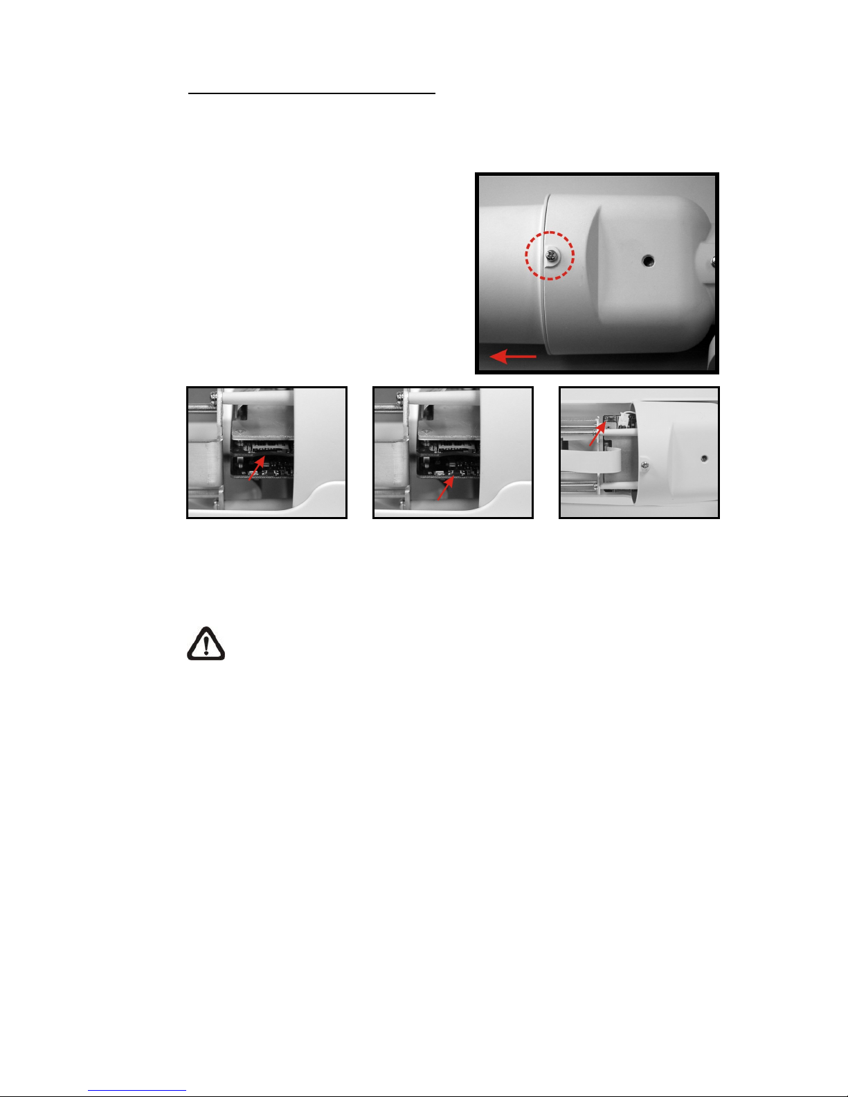
Micro SD Card Slot/ Reset Button
Follow the steps below to reach the Micro SD Card Slot, Reboot Button and
Factory Default Button on IP Camera:
Step 1:
Unscrew the screw on the Camera
Housing and remove the Front
Housing.
Micro SD Card Slot
Factory Default Button
Reboot Button
NOTE: Before installing, please refer to Desiccant User Guide in the
package to place the Desiccant in the Camera to prevent moisture from
condensing on IP Camera’s Glass Cover.

7
2. Camera Cabling
Please follow the instructions below to complete IP Camera connection.
2.1 Connect Power
Please refer to Section: Connectors. Alternatively, connect the Ethernet cable to
the camera’s PoE port and plug the other end of the cable into a PoE switch.
NOTE: If using PoE, make sure Power Sourcing Equipment (PSE) is in
use in the network.
2.2 Connect Ethernet Cable
Use of Category 5 Ethernet cable is recommended for network connection; to
have best transmission quality, cable length shall not exceed 100 meters.
Connect one end of the Ethernet cable to the RJ-45 connector of the IP Camera,
and the other end of the cable to the network switch or PC.
NOTE: In some cases, you may need use an Ethernet crossover cable
when connecting the IP Camera directly to the PC.
Check the status of the link indicator and activity indicator LEDs; if the LEDs are
unlit, please check LAN connection.
Green Link Light indicates good network connection.
Orange Activity Light flashes for network activity indication.
2.3 Connect Alarm I/O
The camera equips one alarm input and one relay output for alarm application.
Please refer to the label on the alarm terminal block and connect the alarm
wiring accordingly.

8
3. Installation
Please read the instructions provided in this chapter thoroughly before installing
the IP Dome Camera.
3.1 Ceiling/Wall Mounting
The IR Bullet IP Camera can be installed directly on a wall or ceiling with the
integrated 2-axis adjustable Bracket Mount. Please note that the wall or ceiling
must have enough strength to support the IP Camera.
Follow the steps below to install the IP Camera:
Step 1:
Unpack the IR Bullet IP Camera package and take out the IP Camera.
Step 2:
Connect the power/Ethernet/alarm/audio wires from ceiling or wall to the
corresponding connectors of the camera’s All-in-one Cable.
Step 3:
Fix the IP Camera’s Bracket on the
ceiling/wall with three supplied self
tapping screws
Step 4:
Use the supplied Inner Hex Wrench
and cross screwdriver to loosen the
hex bolt/screw on the side of the
Bracket Mount and the Camera
Housing to adjust the position of the
IP Camera.
Autres manuels pour 104-466 NIP300
1
Table des matières
Autres manuels Ness Caméra IP


