NEO hsm2host Manuel utilisateur

HSM2HOST 2-Way Wireless Transceiver
V1.0 Installation Guide
Contents:
English ................................ 1
Français .............................. 17
Español ............................... 37
Português ........................... 57
WARNING: This manual contains information on limitations regarding product use
and function and information on the limitations as to liability of the manufacturer. The
entire manual should be carefully read.
D-304886

1
Specifications and Features
• Current Draw: 60mA
• Voltage: Draws current from the PowerSeries Neo alarm controller (10.8VDC to 12.5VDC)
• Frequency: 433MHz (HSM2HOST4), 868MHz (HSM2HOST8), 912-919MHz
(HSM2HOST9UL)
• Zones - can receive signals from up to 128 wireless zones, plus 16 wireless keypads. Also supports
up to 32 wireless keys
• Supervisory - programmable supervisory window
• Can be wired up to 1000 ft. / 230 m from the main panel with 22 AWG wire
• Connects to Corbus
• Compatibility: The HSM2HOST is used with PowerSeries Neo alarm panels
• Operating temperature: 0°C to +49°C (32-122°F)
• Relative humidity: 93% non-condensing
• Separate, built-in wall and case tampers
NOTE: For Commercial BURG (UL) the Supervisory window shall be set to 4 hours.
For Residential Fire (UL/ULC) the Supervisory window shall be set to 200 seconds.
For Residential BURG (UL/ULC) the supervisory window shall be set to 24 hours.
For UL Home Healthcare applications the supervisory window shall be set to 24 hours
Only models operating in the band 912-919 MHz are UL/ULC listed where indicated. Only UL
approved devices are to be used with UL/ULC listed systems.
Compatible Wireless Devices
Please refer to the instruction sheets of the following devices for more information. On the chart
below and throughout this document, x in the model number represents the operating frequency of the
device as follows: 9 (912-919 MHz), 8 (868MHz), 4 (433MHz).
The HSM2HOSTx (x= 4/8/9) can receive signals from the following devices:
Alarm Controllers
PowerSeries Neo alarm Controllers HS2128
HS2064
HS2032
HS2016
Modules
Wireless keypads HS2LCDWFx
HS2LCDWFPx
HS2LCDWFPVx
Wireless Devices
Wireless PG smoke detector PGx926UL
Wireless PG smoke and heat detector PGx916UL
Wireless PG CO detector PGx913
Wireless PG PIR motion detector PGx904(P)UL
Wireless PG PIR + camera motion detector PGx934(P)UL

2
Safety Instructions
• This equipment must be installed by Service Persons only (service person is defined as a person having the
appropriate technical training and experience necessary to be aware of hazards to which that person may be exposed
in performing a task and of measures to minimize the risks to that person or other persons). It must be installed and
used within an environment that provides the pollution degree max 2, over voltages category II, in non-hazardous,
indoor locations only.
• The installer is responsible for instructing the system user in regards to electrical safety precautions when using a
system which includes this equipment and also in regards to each of the following:
• Do not attempt to service this product. Opening or removing covers may expose the user to dangerous volt-
ages or other risks.
• Any servicing shall be referred to service persons only.
• Use authorized accessories only with this equipment.
• Secure the receiver to the building structure before applying power to the alarm controller.
Use adequate mounting means to secure the receiver to the building structure (e.g., plastic/metal anchors and screws).
Only UL/ULC listed devices can be used in UL/ULC listed installations.
HSM2HOST9 is listed for UL Commercial Burglary, Residential Fire, Residential Burglary and Home Health Care,
ULC Residential Fire and Residential Burglary:
UL1610 Central-Station Burglar-Alarm Units
UL1023 Household Burglar-Alarm System Units
UL985 Household Fire Warning System Units
UL1637 Home Health Care Signaling Equipment
ULC-S545-02 Residential Fire Warning System Control Units
ORD-C1023-1974 Household Burglar-Alarm System Units
UL 609 Local Burglar Alarm Units and Systems
UL365 Police Station Connected Burglar Alarm Units and Systems
Wireless PG curtain motion detector PGx924UL
Wireless PG dual tech motion detector PGx984(P)
Wireless PG mirror motion detector PGx974(P)UL
Wireless PG outdoor motion detector PGx994UL
Wireless PG glass break detector PGx912
Wireless PG shock detector PGx935UL
Wireless PG flood detector PGx985UL
Wireless PG temperature detector (indoor use) PGx905UL
Wireless PG key PGx939UL
Wireless PG key PGx929UL
Wireless PG panic key PGx938UL
Wireless PG 2-button key PGx949UL
Wireless PG indoor siren PGx901UL
Wireless PG outdoor siren PGx911UL
Wireless PG repeater PGx920UL
Wireless PG door/window contact PGx975UL
Wireless PG door/window contact w/ AUX PGx945UL

3
Introduction
The HSM2HOSTx two-way wireless transceiver adds wireless capability to PowerSeries Neo alarm
controllers, model HS2128, HS2064, HS2032 or HS2016. This manual describes how to install,
program and maintain the HSM2HOST.
Controls & Indicators
Status LEDs
The LEDs on the front of the HSM2HOST provide feedback regarding the installation, operation and
troubleshooting of the unit. The LEDs function as follows:
Red LED Operation
Module Power Up: On steady during module power-up sequence then off.
Firmware Update: Slow flashing = update in progress
Rapid flashing = update failed
Very rapid flashing = update corrupt, contact distributor
Trouble Condition: • No trouble: 1 rapid flash every 10 seconds.
If troubles are present, a series of flashes occur every 2 seconds. Each
series of flashes indicate troubles as follows:
• 1 flash: Module not enrolled
• 2 flashes: Loss of contact with module for over 60 seconds
• 3 flashes: Corbus low voltage
• 8 flashes: RF interference (jam condition)
Module Confirmation: On steady during module confirmation process.
Placement Test: On steady when location is bad. Off when location is good.
Green LED Operation
Placement Test: On steady when location is suitable. Off when location is unsuitable.
For UL/ULC listed systems, signal must be “Strong”. See
Wireless Device Status Indications on page 9 for details.
Tamper
The HSM2HOST has separate built-in wall and case tampers. The case tamper is disabled by default
on the NA version (enabled on EU version). Section [804][510] option 3 enables or disables the case
tamper. Enable or disable the wall tamper by fastening the breakaway wall tamper bracket securely to
the wall using one of the supplied screws.
The case tamper activates when the case is opened and restores when the case is closed. The wall
tamper on the back of the unit is depressed by the mounting surface when properly installed. If the
unit is removed, the tamper activates. Ensure the mounting surface is smooth and free of obstructions
that block access to the rear of the unit. Electrical wires should not run over or under the module when
it is mounted.
NOTE: The built in wall and case tamper must be installed and enabled for UL/ULC listed
Commercial/ Residential Burglary applications.
NOTE:

4
Setup & Wiring
Choose a Mounting Location
NOTE: Permanently mount the HSM2HOST receiver and wireless devices AFTER
placement testing each device (See “Permanently Mount” on page 5).
Find a place that is:
•dry,
• within operating temperature range,
• central to the proposed placement of all wireless devices,
• as high as possible. The range is reduced if mounted below ground level,
• far from sources of interference, including: electrical noise (computers, televisions, electric
motors, appliances, heating and air conditioning units), large metal objects like heating ducts and
plumbing which may shield the electro-magnetic waves,
• smooth and free of obstructions that block access to the rear of the unit.
Connect the HSM2HOST
CAUTION: Remove all power (AC, DC, telephone lines) from the system while connecting modules
to the Corbus.
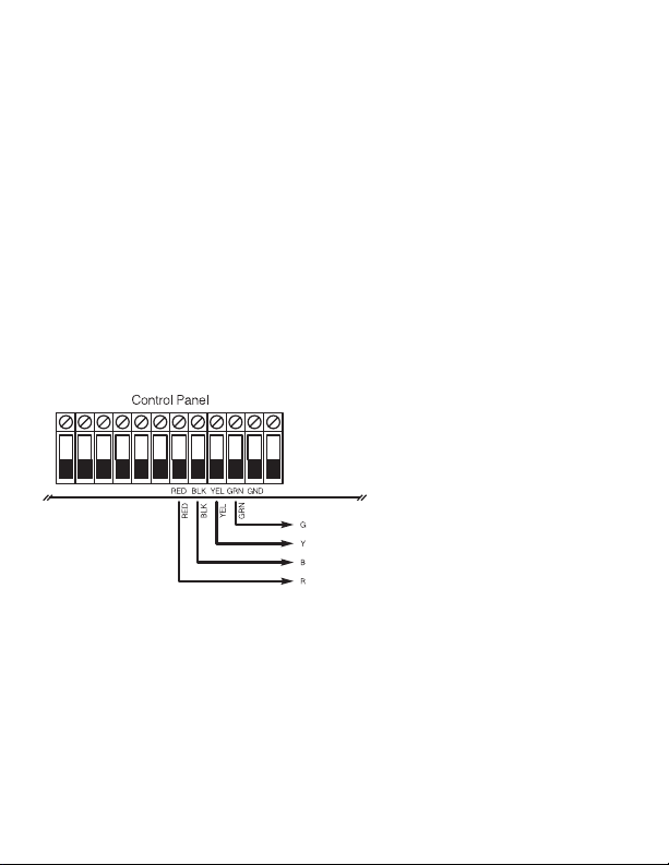
1. With the alarm panel powered down, connect the HSM2HOST to the four-wire Corbus of the
alarm panel according to Figure 1.
2. Once the wiring is complete, power up the security system.
Figure 1: Corbus Wiring
CORBUS TO
HSM2HOST
Enroll The HSM2HOST
The HSM2HOST must be enrolled onto the alarm panel before any wireless devices can be
enrolled.When the alarm system is powered up for the first time, the first keypad or the HSM2HOST
(if using a wireless keypad as the first keypad) can be enrolled. To do this:
1. Once the HSM2HOST is wired to the alarm panel and power has been applied, power up a
wireless keypad.
2. Press any button on the keypad to enroll it on the HSM2HOST. The HSM2HOST is then
automatically enrolled on the alarm panel.
Alternately, enroll the HSM2HOST on the system at any time using the following procedure:
1. Enter Installer Programming section [902][000] (Auto Enroll All Modules).
2. When prompted, press [*] to enroll.

5
To manually enroll,
1. Enter Installer Programming section [902][001] (Enroll Modules).
2. When prompted, key in the serial number found on the back of the HSM2HOST. The module is
enrolled.
Delete the HSM2HOST
To remove the HSM2HOST from the system:
1. Enter Installer Programming section [902][106] (Delete HSM2HOSTx).
2. Press [*] to delete.
Test HSM2HOST Location for RF Interference
With the alarm panel powered up and the HSM2HOST enrolled, enter installer programming section
[904]. Observe the status of the red LED. If the red LED is on, interference levels are high and a new
mounting location should be found. If the red LED is off, interference is low and the location is good.
NOTE: For UL/ULC listed systems, signal must be “Strong”. See Wireless Device Status
Indications on page 9 for details.
Permanently Mount
Once a suitable location is found, mount the HSM2HOST as follows:
1. Pull the Corbus wires through the holes at the back of the cabinet.
2. Mount the cabinet securely to the wall using the three screws supplied.
3. To enable the wall tamper, fasten the breakaway wall tamper bracket securely to the wall using the
supplied screw.
Figure 2: Mounting the HSM2HOST

6
Wireless Device Setup and Programming
[804][000] Enroll Wireless Devices
1. Enter Installer Programming section [804][000].
2. When prompted, either activate the device (see device installation sheet) to enroll immediately or enter
a device ID number. Do the latter to pre-enroll devices then enroll them later at the customer site.
The alarm panel determines the type of device being enrolled and presents the appropriate
programming options.
3. Use the scroll keys or type in the corresponding number to select an option.
4. Scroll through the available selections, key in a number or enter text as appropriate.
5. Press [*] to accept and move to the next option.
6. Once all options are configured, the system prompts to enroll the next device.
7. Repeat the process described above until all wireless devices are enrolled.
[804][001]-[716] Wireless Device Configuration
To configure wireless devices:
1. Enter Installer Programming section [804] then select one of the following sub-sections:
• 001-128 – Configure wireless zones
• 551-556 – Configure wireless sirens
• 601-632 – Configure wireless keys
• 701-716 – Configure wireless keypads
2. Select a device to configure using the scroll keys or go directly to a specific device by entering a
hotkey.
3. Use the scroll buttons or enter a hotkey to select a configuration option for the device. See device
sheets for details.
4. Press [*] to accept and move to the next option.
5. Once all options are configured, the system returns to the base configuration menu.
Repeat the process described above to configure other wireless devices.
[804][801] RF Jam Detect
To configure RF jamming:
1. Enter Installer Programming section [804][801].
Select one of the following options by scrolling or entering the hotkey:
• 00 – Enabled/Disabled
• 01 – UL 20/20-USA
• 02 – EN 30/60-Europe
• 03 – Class 6 30/60-British
2. Press [*] to accept the selection.
3. Press [#] to exit the section.
[804][802] Wireless Supervision Window
For EN installations, 1 hour or 2 hours must be selected.When option 06 is used, which configures
the system to generate fault conditions after a device has been detected as absent for 24 hours, smoke
detectors generate a fault condition after a maximum of 18 hours when the supervision toggle option
is disabled.
To program the Wireless Supervisory Window:
1. Enter Installer Programming section [804][802].
2. Select one of the following options by scrolling or entering the hotkey:
• 00 – Enabled/Disabled

7
• 01 – After 1 Hour
• 02 – After 2 Hours
• 03 – After 4 Hours
• 04 – After 8 Hours
• 05 – After 12 Hours
• 06 – After 24 Hours
3. Press [*] to accept the selection.
4. Press [#] to exit the section.
NOTE: For UL Residential Burglary (UL1023), Home Health Care (UL1637), ULC
Residential Burglary (ULC/ORD-C1023) installations, the maximum Supervision window
shall be set to 24 hours.
For UL Residential Fire (UL985) installations, the maximum supervision window is set to 200s.
For UL Commercial Burglary (UL1610/UL365) and ULC Residential Fire (ULC-S545), the maximum
supervision window shall be set to 4 hours.
[804][810] Wireless Options
To program wireless options:
1. Enter Installer Programming section [804][810].
2. Select one of the following options by scrolling or entering the hotkey:
• 01 – RF Delinquency
• 02 – Wireless Supervisory/ RF Jam Alarm
• 03 – Wireless Tamper
• 04 – 200s Fire Supervision
3. Press [*] to accept the selection and [#] to exit.
[804][841] Motion Cameras
To program wireless options:
1. Enter Installer Programming section [804][841].
Select one of the following options by scrolling or entering the hotkey:
001 Visual Verification On: Alarms trigger image capture from PIR
Cameras
Off: Alarms do not trigger image capture from
PIR Cameras
002 View Time Window 01 Alarm + 5 Minutes
02 Alarm + 15 minutes
03 Alarm + 1 Hour
003 View Other Alarms 01 Fire enabled/disabled
02 Duress enabled/disabled
03 Medical enabled/disabled
04 Panic enabled/disabled

8
[804][901]-[905] Delete Wireless Devices
To delete wireless devices:
1. Enter Installer Programming section [804] then select one of the following sub-sections:
• 901 – Delete wireless zone devices
• 902 – Delete wireless key
• 903 –Delete sirens
• 904 - Delete repeater
• 905 - Delete keypad
2. Select a device to delete using the scroll keys or go directly to a specific device by entering a hotkey.
3. Press [*] to delete or [#] to exit.
[804][921]-[925] Replace Wireless Devices
To replace a wireless device:
1. Enter Installer Programming section [804] then select one of the following sub-sections:
• 921 – Replace wireless zone devices
• 922 – Replace wireless keys
• 923 – Replace sirens
• 924 – Replace repeater
• 925 – Replace keypad
2. Press [*] to select a sub-section. The first available device is displayed.
3. Select a device to replace using the scroll keys or go to a specific device by entering a hotkey.
4. Press [*]. When prompted, activate the device (full enrollment) or enter the device ID (pre-
enrollment). A message is displayed confirming enrollment.
[804][990][001 – 005] Show All Devices
Use this section to review wireless devices enrolled on the system and to view serial numbers
associated with each device.
To review wireless device information:
1. Enter Installer Programming section [804][990] then select one of the following sub-sections:
• [001] – all zones
• [002] – repeaters
• [003] – sirens
• [004] – wireless keys
• [005] – keypads
2. Press [*] to select a wireless device type. The first available device is displayed.
3. Use the scroll keys to view the enrolled devices.
NOTE: This option is not fully supported by LED and ICON keypads.
[804][999] Reset to Factory Defaults
Selecting this option resets HSM2HOST programming to factory default settings.
[904] Placement Testing Wireless Devices
The following test modes are available:
• 001-128 – Test wireless zones
• 520 – Test all repeaters
• 550 – Test all sirens
• 600 – Test all wireless keys
• 700 – Test all keypads

9
Two test results are provided:
• 24-hour: Average results of signal strength testing over a 24-hour period.
• Now: Signal status results of the current test.
During testing, the Ready and Armed LED's flash to indicate data is being received. A flashing Trouble
LED indicates RF interference. The following status indicators may be displayed:
Table 1: Wireless Device Status Indications
LCD Icon* LED+ Status Repeater [905]
Strong 1 9 Strong signal strength Repeater 1
Good 210 Good signal strength Repeater 2
Poor 311 Poor signal strength Repeater 3
1-Way 412 The device is operating in 1-way mode only.
The alarm panel cannot configure or control the
device
Repeater 4
Not Test 513 Displayed as the Now result if no test was
performed.
Repeater 5
None 14 Always displayed as the 24-hour result when
testing wireless keys.
Repeater 6
*For Icon keypads, digit 1 indicates 24-hour test results; digit 2 indicates Now test results.
+For LED keypads, the first digit indicates 24-hour results; the second digit indicates Now test results.
Table des matières
Langues :