NADDOD S2200 Series Manuel utilisateur

NADDOD S3200P/S2200 Series Ethernet
Switches Installation Instruction Manual

NADDOD Pte. Ltd.
i
NADDOD Pte. Ltd. provides customers with all-around technical support and services. Where users, who
purchase products directly from NADDOD, face any problem during the usage, they may contact the local offices
or user service centers of NADDOD, and may also contact the headquarters of the Company directly.
Where readers face any problem about the products of NADDOD , or intend to learn more about other relevant
products of the Company, they may contact us by the following ways:
Website of the Company: http://www.naddod.com/
Technical support hotline: 400-0698-860
Technical support e-mail: tech@naddod.com
Technical file e-mail: tech@naddod.com
Customer complaint hotline: 400-0698-860
Address of headquarters of the Company: 302, Building F1, Optics Valley Software Park, Guanshan 1st Road
East Lake High-tech Zone, Wuhan ,P.R.China
Postcode: 430000
―――――――――――――――――――――――――――――――――――――――――――――
Declaration
Copyright ©2022
NADDOD Pte. Ltd.
Copyright reserved, all rights reserved.
Without written permission of the Company, any unit or individual shall neither extract, copy partial or all of the
content hereof, nor transmit it in any form.
is the registered trademark of NADDOD Pte. Ltd.
Other logos that appear in this manual are properties of their own owners.
Due to the version upgrade of products or other reasons, the content of this manual will be updated irregularly.
Unless otherwise agreed, this manual is only used as usage instruction, and all statements, information and
suggestions herein don't constitute any expressed or implied guarantee

S3200P&S2200 Series Installation Guide
Product Introduction
NADDOD Pte. Ltd.
ii
Foreword
Overview
This document presents product introduction, installation guide, startup after power on,
maintenance and troubleshooting of S3200P & S2200 Series full Gigabyte Ethernet Switches
(hereinafter referred to as S3200P & S2200 Series).
Product Version
The product versions corresponding to this document are as follows.
Product name
Hardware version
S3200P-24T4X
S3200P-48T4X
S2200-24T4X
S2200-48T4X
Stipulations
Symbol Stipulations
The following symbols may appear in the document, of which the meanings are as below.
Symbol
Description
Text marked with this symbol means potential risk that may cause
personal injury if it cannot be avoided.
Text marked with this symbol means potential risk that may cause
equipment trouble, data loss, device performance degradation or
unpredictable results if it is ignored.
Text marked with this symbol delivers additional information to the
body for emphasizing and complementing.

S3200P&S2200 Series Installation Guide
Product Introduction
NADDOD Pte. Ltd.
iii
Symbol
Description
Text marked with this symbol may help you address certain issues
or save your time.
General Format Stipulations
Format
Description
Song
The main body is in Song.
Gothic
Level 1 title, Level 2 title, Level 3 title and Block are in
Gothic.
Regular
Warnings and hints are in Regular.
Lucida Console
Lucida Console format indicates screen output. Additionally,
the data input by users from terminal among the screen
output is displayed in bold font.

S3200P&S2200 Series Installation Guide
Product Introduction
NADDOD Pte. Ltd.
iv
Contents
1 Product Introduction .....................................................................................................................vi
1.1 Product Model Description .............................................................................................................................. vi
1.2 S3200P&S2200 Series Front Panel Description ............................................................................................. vii
1.2.1 S3200P-24T4X ...................................................................................................................................... vii
1.2.2 S3200P-48T4X ..................................................................................................................................... viii
1.2.3 S2200-24T4X ........................................................................................................................................viii
1.2.4 S2200-48T4X ..........................................................................................................................................ix
1.3 S3200P Series Back Panel Description ............................................................................................................ ix
1.3.1 S3200P-24T4X ........................................................................................................................................ix
1.3.2 S3200P-48T4X .........................................................................................................................................x
1.3.3 S2200-24T4X ......................................................................................................................................... 11
1.3.4 S2200-48T4X ......................................................................................................................................... 11
1.4 S3200P&S2200 Series Port Description ......................................................................................................... 11
1.4.1 Service Port ............................................................................................................................................ 11
1.4.2 Management Port ................................................................................................................................... 14
1.5 S3200P&S2200 Series Indicator Description ................................................................................................. 15
1.5.1 System Indicator .....................................................................................................................................15
1.5.2 Power Indicator ...................................................................................................................................... 15
1.5.3 Port Mode Indicator ............................................................................................................................... 16
1.5.4 Ethernet Management Port Indicator ..................................................................................................... 16
1.5.5 10/100/1000BASE-T Self-adapting Ethernet Port Status Indicator .......................................................17
1.5.6 SFP Port/ SFP+ Port Status Indicator .....................................................................................................17
2 Installation Guide ..........................................................................................................................18
2.1 Preparation before Installation ........................................................................................................................ 18
2.1.1 Safety Warning .......................................................................................................................................18
2.1.2 Pre-installation Check ............................................................................................................................ 18
2.1.3 Installation Tools .................................................................................................................................... 21
2.2 Installation ....................................................................................................................................................... 21
2.2.1 Installing by Fixing the Front Suspension Loop onto the Chassis via Chassis Tray............................. 21
2.2.2 Installation and Disassembling of Power Module ................................................................................. 23

S3200P&S2200 Series Installation Guide
Product Introduction
NADDOD Pte. Ltd.
v
2.3 Ground Connection ......................................................................................................................................... 24
3 Initial Startup after Power on of Switches ..................................................................................26
3.1 Building Configuration Environment and Connecting Cables ........................................................................26
3.2 Setting up Terminal Parameters (Windows Hyperterminal) ........................................................................... 27
3.3 Setting up Port Parameters (SecureCRT)........................................................................................................ 29
3.4 Power on of Switch ......................................................................................................................................... 31
4 Technical Data ............................................................................................................................... 34
4.1 Overall Parameters .......................................................................................................................................... 34
4.2 Laser Safety Class ........................................................................................................................................... 35
4.3 Reliability Indicators ....................................................................................................................................... 36
4.4 EMC Indicators ............................................................................................................................................... 36
4.5 Safety Standards .............................................................................................................................................. 36
4.6 Environment Requirements ............................................................................................................................. 36
4.6.1 Storage Conditions ................................................................................................................................. 37
4.6.2 Transport Environment .......................................................................................................................... 38
4.6.3 Operating Environment ..........................................................................................................................38
Climatic Circumstance .......................................................................................................................................... 38
4.7 Standards and Protocols .................................................................................................................................. 39
5 Install License ................................................................................................................................41
6 Maintenance and Troubleshooting .............................................................................................. 42
6.1 Troubleshooting of Configuration System Failure ..........................................................................................42

S3200P&S2200 Series Installation Guide
Product Introduction
NADDOD Pte. Ltd.
vi
1Product Introduction
S2200 & S3200P Series Ethernet Switches are new generation high-performance Gigabyte
Ethernet Switches launched by Naddod Networking, which provide rich port forms such as
10/100/1000Base-T self-adapting Ethernet port and 10G SFP+ optical interface, support
pluggable dual power supply, and are widely applied in network environment of
high-performance, high reliability, high port density and convenience in installation to address
users’ needs of enterprise-class access or tandem low-end switches.
1.1 Product Model Description
Table 1-1 S3200P&S2200 Switches
Product model
Description
S3200P-24T4X
Standard 1RU 19-inch chassis
24 10/100/1000 Base-T ports, including 4 Combo ports
and 4 10G SFP+ ports
POE+
Pluggable dual power supply
S3200P-48T4X
Standard 1RU 19-inch chassis
48 10/100/1000 Base-T ports, including 4 10G SFP+
ports
POE+
Pluggable dual power supply
S2200-24T4X
Standard 1RU 19-inch chassis
24 10/100/1000 Base-T ports, including 4 10G SFP+
ports
Built-in fixed single power supply
S3200P&S2200 Series Installation Guide
Product Introduction
NADDOD Pte. Ltd.
vii
Product model
Description
S2200-48T4X
Standard 1RU 19-inch chassis
48 10/100/1000 Base-T ports, including 4 10G SFP+
ports
Built-in fixed single power supply
1.2 S3200P&S2200 Series Front Panel Description
1.2.1 S3200P-24T4X
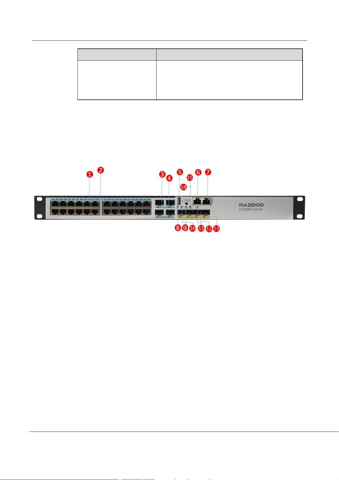
Figure 1-1 Schematic Diagram of S3200P-24T4X Front Panel
(1): 10/100/1000BASE-T self-adapting Ethernet port
(2): 10/100/1000BASE-T self-adapting Ethernet port status
indicator
(3): SFP Combo port
(4): SFP port status indicator
(5): USB port
(6): Ethernet management port
(7): CONSOLE port
(8): System status indicator (SYS)
(9): Pluggable power module 1 status indicator (PWR1)
(10): Pluggable power module 2 status indicator (PWR2)
(11): Ethernet management port status indicator
(ACT/LINK)
(12): 10G SFP+ port
(13): 10G SFP+ port status indicator
(14): Mode switch (POE lamp/link&ACT lamp)
(15): Mode switch lamp (POE lamp/link&ACT lamp)

S3200P&S2200 Series Installation Guide
Product Introduction
NADDOD Pte. Ltd.
viii
1.2.2 S3200P-48T4X
Figure 1-2 Schematic Diagram of S3200P-48T4X Front Panel
(1): 10/100/1000BASE-T self-adapting Ethernet port
(2): 10/100/1000BASE-T self-adapting Ethernet port status
indicator
(3): USB port
(4): Ethernet management port
(5): CONSOLE port
(6): System status indicator (SYS)
(7): Pluggable power module 1 status indicator (PWR1)
(8): Pluggable power module 2 status indicator (PWR2)
(9): Ethernet management port status indicator
(ACT/LINK)
(10): 10G SFP+ port
(11): 10G SFP+ port status indicator
(12): Mode switch (POE lamp/link&ACT lamp)
(13): Mode switch lamp (POE lamp/link&ACT lamp)
1.2.3 S2200-24T4X
Figure 1-3 Schematic Diagram of S2200-24T4X Front Panel
(1): 10/100/1000BASE-T self-adapting Ethernet port
(2): Port number direction indicator
(3): 10G SFP+ port
(4): CONSOLE port
(5): 10/100/1000BASE-T Ethernet port status indicator
(6): 10G SFP+ port status indicator
(7): System status indicator (SYS)

S3200P&S2200 Series Installation Guide
Product Introduction
NADDOD Pte. Ltd.
ix
1.2.4 S2200-48T4X
Figure 1-4 Schematic Diagram of S2200-48T4X Front Panel
(1): 10/100/1000BASE-T self-adapting Ethernet port
(2): 10/100/1000BASE-T Ethernet port status indicator
(3): Reset button
(4): System status indicator (SYS)
(5): Power indicator (PWR)
(6): 10G SFP+ port
(7): 10G SFP+ port status indicator
(8): CONSOLE port
1.3 S3200P Series Back Panel Description
1.3.1 S3200P-24T4X
Figure 1-5 Schematic Diagram of S3200P-24T4X Back Panel
(1): Grounding screw
(2): Cooling fan
(3): Pluggable power module 1 (PSU1)
(4): Pluggable power module 2 (PSU2)
Ce manuel convient aux modèles suivants
5
Table des matières
Autres manuels NADDOD Changer


