Nabco Acusensor 3 Manuel utilisateur

S82 W18717 Gemini Drive
Muskego, WI 53150
Phone: (877) 622-2694
Fax: (888) 679-3319
www.nabcoentrances.com
Technical Assistance: 866-622-8325
Instruction
Manual
Acusensor 3
P/N 15-8911-3
January 16, 2015 Revision
Instruction Manual
WARNING
● Do Turn OFF all power to the Automatic Door if Safety System is not working.
● Instruct the Owner to keep all power turned OFF until corrective action can be achieved by a NABCO trained technician.
Failure to follow these practices may result in serious consequences.
● NEVER leave a Door operating without all Safety detection systems operational.
DN0359
NOT FOR USE AS A SWING DOOR SAFETY SENSOR
This Sensor does not have adequate pattern detection for use as a safety presence detector
on the Pull Side of Swing door.

Page 2 of 15 1-877-622-2697 WWW.NABCOENTRANCES.COM
Acusensor 3
____________________________________________________________________________________________
CAUTION:
Do not install, operate or service this product unless you have read and understood
the Safety Practices, Warnings, Installation and Operating Instructions contained in
this manual. Failure to do so may result in property damage or bodily injury.
CAUTION:
The purpose of this manual is to familiarize the purchaser with the proper
installation and operation of this system. It is essential that this equipment be
properly installed and operational before the door is used by the public. It is your
responsibility to inspect the operation of the entrance system to be sure it complies
with any applicable standards. In the United States, ANSI Standard 156.10 and
156.19 usually cover the operation of the doors.
Instruct the building owners/operator on the essentials of the operation of the door
and this device. The owner should follow these instructions to determine whether the
NOT FOR USE AS A SWING DOOR SAFETY SENSOR
This Sensor does not have adequate pattern detection for use as a safety presence detector
on the Pull Side of Swing door.

Page 3 of 15 1-877-622-2697 WWW.NABCOENTRANCES.COM
Acusensor 3
____________________________________________________________________________________________
Contents
A. General Specifications 4
B. Appearance and Dimensions 5
C. Installation and Adjustment
1. Installation 6
2. Wiring 6
3. Customized Settings
a) Setting up depth coverage 7
b) Setting up width coverage 9
c) Setting up operation mode
1) Setting up interference prevention modes 10
2) Sensitivity setting 11
3) Presence detection time 11
4. Turning ON the power 12
5. LED Indicator 13
6. Usage Tips 13
7. Trouble shooting 15

Page 4 of 15 1-877-622-2697 WWW.NABCOENTRANCES.COM
Acusensor 3
____________________________________________________________________________________________
A. Specifications
Part Description Acusensor 3
Part Number 14-8902-3
Sensing System Active reflective infrared system (Motion / Presence)
Power source 12 to 24V AC or DC Class 2
Recommended
Temperature Range -20 to +55°C (-4 to 131°F)
Power consumption <2.5VA @24VAC, <100mA @12VDC)
Output Contacts
Rating
Form A relay, 50V 0.1A Max. (Resistance load)
No Detection: “OPEN”, Detection: “CLOSED”,
Power failure: “OPEN”
Mounting height 6'6" (2m) to 9'10" (3m)
Detection area
(when mounted at
the height of 118”)
Max. depth: 74.8” Max. width: 130.7”
See page 10, figure 10 for more details
Output display
Green / Stand-by
Red / 1st Row Detection Active
Orange / 2nd Row Detection Active
See page 13 for more details
Standstill memory
time (learn time) 2 sec, 10 sec, 30sec, and 90sec
Output holding time 0.5 seconds
Weight Approximately 1/2 lbs (8.5oz)
Color Black

Page 5 of 15 1-877-622-2697 WWW.NABCOENTRANCES.COM
Acusensor 3
____________________________________________________________________________________________
B. Appearances and Dimensions
Figure 1 - Appearance
Figure 2 – Shown with cover removed
DN0359
DN0359

Page 6 of 15 1-877-622-2697 WWW.NABCOENTRANCES.COM
Acusensor 3
____________________________________________________________________________________________
C. Installation and Adjustments
1. Installation
1. Affix the Mounting Template to the mounting surface (Figure 3).
(When mounting on a header, do not locate the sensor higher than 4.5 inches
above the bottom edge of the header as the header can block the detecting area.)
2. Drill two mounting holes (ø 3.4mm or 1/8”).
3. Drill a wiring hole (ø 8mm or 5/16”) for the sensor harness.
4. After drilling the holes, remove the Mounting Template
CAUTION: To prevent electrical shock, make sure that there are no
electrical wires of other products in the area close to the place
where you are going to drill.
Also, be sure that the mounting height is within the value
of those in "SPECIFICATIONS” on page 4.
2. Wiring
1. Plug the Acusensor 3 Harness (P.N. 22-9184, Figure 4) into the 4 pin
connector on the Acusensor 3.
2. Connect the Black and Red power wires to a class 2 transformer,
or the Brown & Red 12 volt wires on a Microprocessor U series control ,
or other suitable power source.
3. Attach the White and Green wires to the activation or presence input
of the door control.
4. Turn on the power and wait a minimum 10 seconds for the sensor to
calibrate.
Note: There cannot be any motion within the sensing zone during this time.
Figure 3
Figure 4
DN0359
Acusensor Harness P/N 22-9184
DN 0343.5
Form A relay Output, 50V 0.1A Max. (Resistance Load)
Black
White
Power Supply 12 to 24V AC / DC
Red
Green

Page 7 of 15 1-877-622-2697 WWW.NABCOENTRANCES.COM
Acusensor 3
____________________________________________________________________________________________
3. Customized Settings
The following information describes how to change the settings for depth
of coverage, width of coverage, sensitivity and memory. Any changes to
these settings that are made on site by the installer are the responsibility
of the installer. Proper system operation must be verified according to
ANSI Standard 156.10 and 156.19 or any local codes that apply to door
operation.
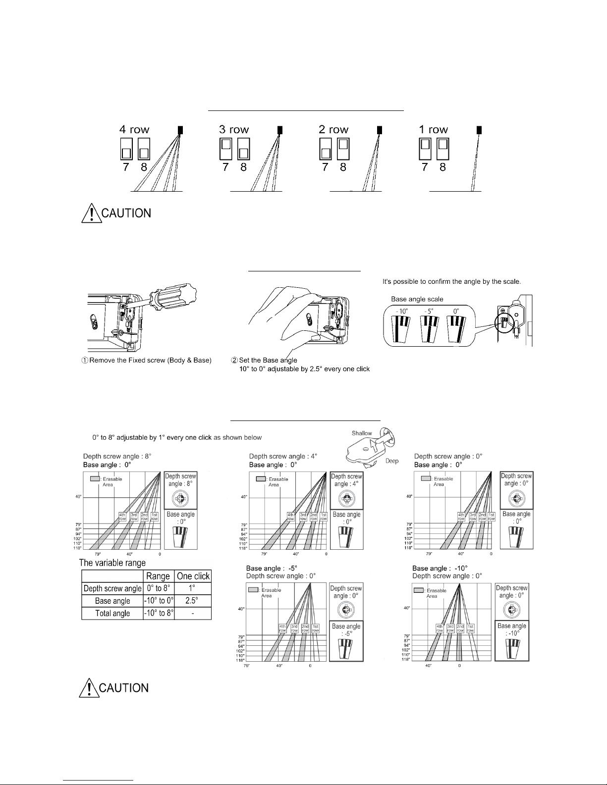
a) Setting up for Depth Coverage
There are three ways to adjust the depth coverage: row settings (dip
switches 7 and 8), base angle, and adjustment of the depth screw.
(See figures 5,6,7 on following page)
As an Activation Sensor
When the Acusensor 3 is intended to be used as a door activating
device, the depth of coverage should comply with ANSI requirements.
When other sensors are being used for the activation function, it may be
desirable (but not necessarily required) to reduce the sensing coverage
area of the Acusensor 3. Adequate threshold coverage might be achieved
by setting the various area settings. Coverage should always be checked
to be sure it is adequate. For best detection of slow moving pedestrians or
objects, the sensitivity option should be on Medium or High.
The width and depth of coverage for an actual installation may vary.
This is typically the result of:
1. A variance in mounting height
2. Normal manufacturing and component tolerances
3. Variances in field measurements, procedures and
conditions from ANSI standards.
4. Use of spacers for mounting

Page 8 of 15 1-877-622-2697 WWW.NABCOENTRANCES.COM
Acusensor 3
____________________________________________________________________________________________
Delayed activation can occur as rows are eliminated
When detection area is tilted toward the door, the bottom edge of the header can block the
sensor pattern if the sensor is installed too high on the header. DO NOT install sensor higher
than 4.5 inches above the bottom edge of the header.
Figure 5
Figure 6
Set the rows using dipswitches 7 and 8
Setting the base angle
DN0359
DN0359
DN0359
DN0359
Figure 7 Setting the depth screw angle

Page 9 of 15 1-877-622-2697 WWW.NABCOENTRANCES.COM
Acusensor 3
____________________________________________________________________________________________
To adjust the pattern width
Areas 1 and 2 can be eliminated and/or areas 7 and 8.
(1 and 2 cannot be separated, neither can 7 and 8)
To adjust the width angle
Use the adjustment tool as shown below to change the width angle.
±7° can be achieved in 3.5° steps each click ( Right / Left )
Mounting
Height
79" 87" 94" 102" 110" 118"
A 6.3" 6.7" 7.5" 7.9" 8.7" 9.4"
B 16.5" 18.1" 20" 21.7" 23.2" 25.2"
C 31.5" 34.6" 37.8" 40.9" 44.1" 47.6"
D 49.6" 54.7" 59.8" 64.6" 69.7" 74.8"
E87" 95.7" 104.3" 113" 121.7" 130.7"
F 62.6" 68.9" 75.2" 81.5" 87.8" 94.1"
G 40.9" 44.9" 48.8" 53.1" 57.1" 61.4"
Z 1.6" 1.6" 1.8" 2" 2.2" 2.4"
See below for areas affected
b) Setting up for Width Coverage
The area width can be adjusted by eliminating the outer areas of detection. (See figures 8,9)
The angle of the area can also be adjusted as shown below. (See figure 9)
Figure 8
Figure 9
Figure 10 Coverage Chart
DN0359
DN0359
DN0359

Page 10 of 15 1-877-622-2697 WWW.NABCOENTRANCES.COM
Acusensor 3
____________________________________________________________________________________________
c) Operation Mode Set up
1) Mutual Interference Prevention Setting
Sensors placed close to each other should be set to different
Interference Prevention Settings
When multiple Acusensor 3’s are used in close proximity to each other,
such as in a vestibule, the use of different modes will help prevent mutual
interference. Using the mode switch, four modes are possible through a
combination of positions on switches 3 and 4. Following is an example of
one combination which might be used in a vestibule. (Figure 12)
Sensors facing
each other or
next to each
othershould
always be set to
different modes
Figure 11
Figure 12
DN0359
DN0359
Autres manuels pour Acusensor 3
1
Table des matières
Autres manuels Nabco Système d'ouverture de porte

Nabco
Nabco ICU 2400 Manuel utilisateur

Nabco
Nabco GT20 Manuel du propriétaire

Nabco
Nabco 710 Manuel utilisateur

Nabco
Nabco GYRO TECH GT-1175 Manuel utilisateur

Nabco
Nabco GYRO TECH GT-1175 Manuel utilisateur

Nabco
Nabco GT 300 Manuel utilisateur

Nabco
Nabco GT20 Manuel utilisateur

Nabco
Nabco GT20 8300 Manuel utilisateur

Nabco
Nabco C-00139 Manuel utilisateur

Nabco
Nabco GT20 Manuel du propriétaire


