NA MultiFlash Series Manuel utilisateur


1. INTRODUCTION
PRODUCT OVERVIEW
MultiFlash indoor LED fixtures are combination wash/strobe/blinders with over 1000 Watts of LED RG W
brightness, 58,000 lumens, instantaneous color mixing, and 1200Hz refresh rate for smooth on-camera
dimming. Q+ Technology increases the brightness with practically no fan noise. Its “Theatre Mode” is effectively
silent, yet still 8% brighter than the original MultiFlash! One MultiFlash LED fixture does the job of many
conventional LED fixtures, saving setup time and labor. Just a few of the features include:
•Simultaneous color wash, strobe, and blinder in ONE fixture! – saves labor, time, space, cost
•Instantaneous RG W color mixing with 1200Hz refresh rate – smooth on-camera dimming
•Pixel-map feature – up to 12 (MultiFlash / MultiFlash Q+ / MultiFlash LR Q+/ MultiFlash Q+ Rayzr
100cm), 6 (MultiFlash Q+ Rayzr 50cm) or 4 (MultiFlash M3) discrete, individually-controlled LED
sections.
•Optimized 36° beam width. 20°, 54°, and 70°options available.
UNPACKING INSTRUCTIONS
Upon receipt of the fixture, carefully unpack the carton and check the contents to ensure that all parts are
present and in good condition. Notify the shipper immediately and retain packing material for inspection if any
parts appear to be damaged from shipping or if the carton itself shows signs of mishandling. Save the carton
and all packing materials. In the event that a fixture must be returned to the factory, it is important that the fixture
be returned in the original factory box and packing.
POWER REQUIREMENTS
efore powering the unit, make sure the line voltage is within the range of accepted voltages. This fixture
accommodates 100-240VAC, 50/60Hz. All fixtures must be powered directly from a switched circuit and
cannot be operated with a rheostat (variable resistor) or dimmer circuit, even if the rheostat or dimmer
channel is used solely as a 0-100% switch.
When powered up, MultiFlash performs a pre-programmed internal test. On initial power- up the factory
default DMX address appears on the display screen and MultiFlash is ready for operation. After initial power-
up, the last-saved DMX address will appear.
FREQUENCY SETTING
Depending on location, change the Default Frequency setting to match the mains power (e.g., US and
Canada should be set at 60Hz). Proper frequency setting will ensure minimum amount of visible artifacts
when using MultiFlash on camera.
2

Safety Instruct ons
● Please keep this user guide for future consultation. If you sell the unit to another user, be sure that they
also receive this instruction booklet.
● Always make sure that you are connecting to the proper voltage, and that the line voltage you are
connecting to is not higher than that stated on the decal or rear panel of the fixture.
● Make sure there are no flammable materials close to the unit while operating.
● Always disconnect from the power source before servicing or replacing fuses and be sure to replace with
same fuse type
● Secure the fixture to what you have attached it to using a safety chain.
● Maximum ambient temperature is 40°C. Do not operate fixture at temperatures higher than this.
● In the event of a serious operating problem, stop using the unit immediately. Never try to repair the unit
by yourself. Repairs carried out by an unskilled person can lead to damage or malfunction. Please
contact the nearest authorized technical assistance center. Always use the same type of spare parts.
● Do not connect the device to a dimmer rack.
● Make sure the power cord is never crimped or damaged.
● Never disconnect the power cord by pulling or tugging on the cord.
● Avoid direct eye exposure to the light source while it is on.
Caution!
There are no user serviceable parts inside the unit.
Do not open the housing or attempt any repairs yourself. In the unlikely event your unit may require
service, please contact your local distributor.
Techn cal Features / Descr pt on
•MultiFlash / MultiFlash Q+: 96 10W RG W Cree® LEDs, divided into 2, 3, 4, 6 or 12 pixels
•MultiFlash M3: 32 10W RG W Cree LEDs, divided into 1, 2, or 4 pixels
•MultiFlash LR Q+: 108 10W RG W Cree LEDs, divided into 1, 2, 3, 4, 6, or 12 pixels
•MultiFlash Q+ Rayzr 100cm: 36 10W RG W Cree LEDs, divided into 1, 2, 3, 4, 6, or 12 pixels
•MultiFlash Q+ Rayzr 50cm: 18 10W RG W Cree LEDs, divided into 1, 2, 3, or 6 pixels
•Variable intensity control 0-100% in 8bit or 16bit control modes
•eam spread: 36° standard. Optional beam widths available: 20°, 54°, and 70°
•Refresh rate: 1200HZ
•Flash Duration control 0-650ms flashes per second
•Flash Rate control 0-16.7Hz (50Hz) / 0-20Hz (60Hz)
•Continuous blinder/wash effect
•Flash intensity curve selection
•User definable fades
•LCD control panel display with four control buttons
•RDM available in MultiFlash RDM, MultiFlash M3, MultiFlash Q+, both MultiFlash Rayzr Q+ and
MultiFlash LR Q+ (not available in early versions of the original MultiFlash)
3

2. SETUP
FUSE REPLACEMENT
MultiFlash, MultiFlash Q+, MultiFlash LR Q+, both MultiFlash Q+ Rayzr, and MultiFlash M3 use a 12A 250V
slow-blow fuse (5x20mm). To replace fuse:
1. With a screwdriver turn the fuse cap counter-clockwise to remove fuse cap with fuse.
2. Replace fuse attached to fuse cap.
3. Reinsert fuse cap with new fuse and tighten clockwise.
FIXTURE LINKING
A DMX data link is needed to operate one or more fixtures via a DMX-512 lighting console. The combined
number of channels required by all the fixtures on a DMX data link determines the number of fixtures the
DMX data link can support.
Important: ixtures on a DMX data link must be daisy -chained in one single line. To comply with the
EIA-485 standard, no more than 32 devices should be connected on one data link. Connecting more
than 32 fixtures on one serial data link without the use of a DMX optically-isolated splitter may result in
deterioration of the digital DMX signal.
Maximum recommended DMX data link distance between fixtures: 984 ft. (300 meters).
POWER LINKING (MultiFlash M , MultiFlash Rayzr)
The MultiFlash Jr and MultiFlash Rayzr has Neutrik® PowerCon IN and THRU connections allowing power
linking (daisy-chaining). Depending on the power provided, you should not exceed the power threshold.
Max. 5 units 100-120V; max. 10 units 208-240V for MultiFlash Jr.
Max. 5 units 100-120V; max. 10 units 208-240V for MultiFlash Q+ Rayzr 50cm.
Max. 3 units 100-120V; max. 6 units 208-240V for MultiFlash Q+ Rayzr 100cm.
4

SETTING UP A DMX SERIAL DATA LINK
1) Connect the male 5-pin XLR connector of the data cable to the female 5-pin XLR output of the DMX
console. Connect the other end of the data cable (female 5-pin XLR) to the male 5-pin XLR connector
located on the NA MultiFlash.
2) Connect from the fixture output as stated above to the input of the following fixture, and so forth.
3) Continue linking until the last fixture is connected in your DMX signal data chain.
FIXTURE MOUNTING
Orientation
MultiFlash, MultiFlash Q+, MultiFlash Rayzr and MultiFlash Jr fixtures may be mounted in any position. Each
have a yoke with mounting hole for clamps or couplers. The MultiFlash LR Q+ comes with a bar yoke and will
also operate in any orientation. Always make sure there is adequate room for ventilation. Do not obstruct the
unit’s fan or vents.
Support Stand
Always use a professional stand rated to support weight greater than the fixture (see technical
specifications). Attach a TVMP spigot to the yoke of the MultiFlash or MultiFlash M3 and mount on
the stand.
Rigging – Always consult a certified rigging specialist before suspending any fixture overhead!
Use C- or O-type clamps for attaching to truss. It is important never to obstruct the fan or
vents pathway. Adjust the angle of the fixture by loosening both knobs and tilting the
fixture. After finding the desired position, retighten both knobs.
•Always use safety cables!
•When selecting installation location, consider routine maintenance.
•Never mount fixture where it will be exposed to moisture, high humidity, extreme temperatures, or
restricted ventilation.
5

. OPERATING INSTRUCTIONS
CONTROL PANEL NAVIGATION
Access control panel functions using the four control panel buttons located directly underneath the LCD
display
The Control Panel LCD Display shows the menu items selected from the menu map (see page 9). When a
menu function is selected, the display will show the first available option for the selected menu function. To
select a menu item, press <MENU>.
Press and hold the <MENU> button to scroll through the top level menu items. This is the top of the menu map.
Use the <UP> and <DOWN> buttons, located to the right of the LCD screen, to navigate the menu map and
menu options. Press the <MENU> button to access the menu function currently displayed or to enable a menu
option. To return to the top of the menu map or menu without changing the value, press the <X> button.
Main Menu Functions: Main Menu Functions: MultiFlash, MultiFlash Q+, MultiFlash LR Q+, MultiFlash Q+
Rayzr.
DMX Address – DMX address selection
Control – Control mode selection menu
Manual – Manual Control
Demo – Demonstration scenes
Config – Configuration Menu
Main Menu Functions: MultiFlash M
DMX Address – DMX address selection
DMX Source – Wireless or wired
Control – Control mode selection menu
Manual – Manual Control
Demo – Demonstration scenes
Config – Configuration Menu
During normal operation, the Control Panel LED Display indicates DMX start address. When the DMX signal is
not connected, or if the MultiFlash is not receiving a DMX signal, the address blinks RED.
6

Menu Map – Mult Flash, Mult Flash Q+, Mult Flash LR Q+,
Mult Flash Rayzr
7

Menu Map – Mult Flash JR
8

MENU FUNCTION DESCRIPTION
DMX Address – To set the required DMX address, open the Main Menu:
1) Press and hold <MENU> button to open the Main Menu.
2) Use <UP> and <DOWN> buttons to find the DMX address function.
3) Press <SELECT> button to access the DMX address value change submenu.
4) Use <UP> and <DOWN> buttons to set necessary DMX address value (e.g. 198).
5) Use <SELECT> button to confirm the new DMX address.
6) Main Menu will appear. Press <EXIT> button to return fixture at work-state.
9
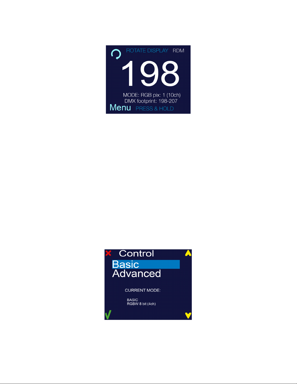
7) The work-state control panel display shows current DMX address (in this example 198). Additional info
is displayed under the DMX address: Selected control mode, channels used by this mode, and
occupied DMX addresses (DMX footprint).
In this example MODE: RG pix:1 (10ch) DMX footprint: 198 - 207 (meaning: RG control mode with 1 pixel
using 10 DMX channels uses DMX 198 to 207).
DMX Source – This device supports two DMX controlling modes through wired connection (DMX cable w/
XLR 5-pin connector).
To set required DMX source, you must:
1) Press and hold <MENU> button to open the Main Menu.
2) Use <UP> and <DOWN> buttons to find the DMX Source submenu and press <SELECT> button.
Control – MultiFlash fixtures are two fixtures in one (strobe and a wash/blinder fixture). In each of the control
modes, the fixture occupies varying numbers of DMX channels and has different control channels. To enter the
Control submenu, follow these steps:
1) Press and hold <MENU> button to open the Main Menu.
2) Use <UP> and <DOWN> buttons to find the Control submenu.
3) Press <SELECT> button to access the Control submenu.
4) Choose the correct control mode. Select from asic or Advanced.
When the control submenu is opened, there are two settings to choose from:
Basic – This mode allows for simple control of the fixture as a linder/Wash fixture, or as a Strobe.
Advanced – This mode allows for independent control of linder/Wash functions, and the Strobe functions. This
mode also allows for independent color and intensity control of every segment of LEDs independently.
10
Ce manuel convient aux modèles suivants
5
Table des matières
Manuels Projecteur populaires d'autres marques


Panasonic
Panasonic PTL735NTU - LCD PROJECTOR-NETWORK IB Manuel utilisateur

NEC
NEC NP600S EDU Manuel utilisateur

BenQ
BenQ SH753P Manuel utilisateur

Eiki
Eiki EK-623U series Manuel utilisateur

Epson
Epson PowerLite Pro Cinema 6020UB Manuel utilisateur

Epson
Epson PowerLite Home Cinema 705HD Manuel utilisateur


