MyBinding Standard APC45 Programmable Manuel utilisateur

Instruction Manual
Provided By
http://www.MyBinding.com
http://www.MyBindingBlog.com
Standard APC45
Programmable
Paper Cutter


I
• This manual is designed to help you to install, operate and maintain the APC-45 Paper
Cutter. Please read and understand this manual, and keep it in a safe and convenient
place.
• Do not operate the APC-45 until you read and understand the instructions in this
manual.
• Horizon International Inc. shall not be liable for incidental consequential damages
resulting from: improper or inadequate maintenance by the customer unauthorized
modification or misuse, or operation outside of the environmental specifications for the
product.
• Horizon International Inc. pursues a policy of continuing improvement in design and
performance of the product. Therefore, the product design and specifications are
subject to change without prior notice and without our legal obligation.
• All rights are reserved. No part of this manual may be photocopied, reproduced or
translated to another language without the prior written consent of Horizon
International Inc.
Important Information
081208/APC45/06E/NO/HF/KY/F7/I9/P7 UM204023-06
P
APER CUTTE
RPAPER CUTTER
APC- 45

II
Horizon International Inc. cannot anticipate every possible situation that might involve a
potential hazard. The instructions in this manual and warning labels on the machine are
therefore not all inclusive.
All equipment shall be locked out or tagged out to protect against accidental or inadvertent
operation when such operation could cause injury to personnel. Do not attempt to operate
any switch, valve, or other energy isolating device where it is locked or tagged out.
Do not operate the machines when any covers are removed.
Some of the drawings in this manual show the machine with the covers removed to
explain some of the details inside the machine. Never operate the machine with the covers
removed.
Safety Precautions
Safety precautions are indicated in this manual as follows:
The term WARNING indicates a potentially hazardous situation which, if not
avoided, could result in death or serious injury.
The term CAUTION indicates a potentially hazardous situation which, if not
avoided, may result in serious injury, or damage to the machine.
This symbol indicates a note which includes important information. Follow
the note to operate the machine safely.
This symbol indicates a prohibited action. Do not perform any prohibited
action.
This symbol indicates an essential procedure. Follow the procedure to
operate the machine safely.
Important
• This lists the range of acceptable values and operating
conditions.
Attention
• This information will help you to avoid problems with the
machine or help you learn how to operate the machine.
Note
• Refer to this note when you operate the machine.
Additional
Information
• This explains a mechanism in the machine.

III
Safety Operation Precautions
WARNING for Operation
This machine must be operated by just one person at a time.
Various safety devices are installed on this machine. If any of these are bypassed or
removed, this may cause severe accident and personal injury.
Each operator should be familiar with the safety instructions, be aware of the potential
dangers, and have sufficient knowledge of how to manage an accident. Anyone who
does not have this training should not operate the machine.
Before starting the machine, be sure to perform the checks described in Chapter 2:
Safety Checks. When loading the sheets on the table and setting the sheet position, get
your foot off from the foot pedal.
CAUTION for Operation
Do not cut anything besides paper. This may damage the machine.
If you turn the power switch Off, wait 10 seconds or more before turning it On again.
Do not get on, or step on the foot pedal with great force. The machine may be dam-
aged.
CAUTION for Maintenance
Do not apply too much grease. Filled grease may stain the paper.

IV
Space Required for Installation
As the electrical parts are installed on the lower left of the machine, repair work may be done from the
right side. Allow about 600 to 700 mm (23.7 to 27.6") on the left side of the machine if it is possible.
In addition, when you adjust the knife angle, you need to insert the tool into the machine from the left
side. Allow about 200 mm (7.9”) on the left side.
Allow about 100 to 200 mm (4 to 7.9”) on the right side and the rear.
Antivibration Cushion
If you use the antivibration cushions, place the cushions under the four corners of the machine. In addi-
tion, place the supplied wedges under the machine to keep the machine in a horizontal position.
CAUTION for Installation
Ground Terminal
Make sure to connect
the accessory ground
wire.
If the ground wire is
not connected, the let-
ters on the guide win-
dow may not appear
correctly.
Make sure to connect the ground wire.
770 (30.4")
880 (34.7")
100 - 200
(4" - 7.9") 100 - 200
(4" - 7.9")
600 - 700
(23.7" - 27.6")
mm (inch)
Front

V
CONTENTS
Important Information........................................................................................ I
Safety Precautions............................................................................................ II
Safety Operation Precautions......................................................................... III
1. Machine Descriptions .................................................................................. 1
1-1 Machine Descriptions .............................................................................................1
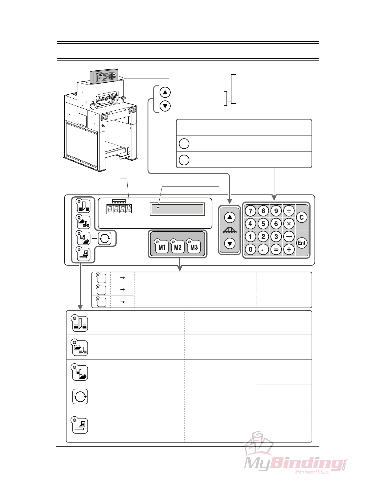
1-2 Control Panel Descriptions .....................................................................................2
1-3 Cutting Mechanism ................................................................................................3
2. Safety Checks ............................................................................................... 5
2-1 Check the Power Switch ........................................................................................5
2-2 Check the Cutting Buttons .....................................................................................7
2-3 Check the Beam Light Sensors ..............................................................................8
2-4 Check the Control Panel ........................................................................................9
2-5 Check the Foot Pedal ........................................................................................... 10
3. Operation Procedures ............................................................................... 11
3-1 Cutting Operation on the Cutting Line .................................................................. 11
3-2 Cutting Operation by Entering a Value ................................................................. 14
3-3 Cutting Operation by Programmed Value ............................................................17
3-4 Function Cutting ...................................................................................................20
3-5 Compression Operation ....................................................................................... 22
3-6 Creating a Cutting Program .................................................................................23
3-7 Checking the Counter ..........................................................................................30
3-8 Knife Replacement Message ...............................................................................31
4. Replacement and Adjustment.................................................................... 33
4-1 Knife Lower Limit Adjustment ............................................................................... 33
4-2 Knife Angle Adjustment ........................................................................................35
4-3 Cutting Stick Replacement ...................................................................................37
5. Troubleshooting.......................................................................................... 39
5-1 An Error Message Appears ..................................................................................39
5-2 Problems and Remedies ...................................................................................... 40
5-2-1 Stain, Diagonal Line, Pressing Mark and Uncut of the Sheets ............................... 40
6. Maintenance ................................................................................................ 43
6-1 Lubrication ............................................................................................................ 43
7. Appendix...................................................................................................... 45
7-1 Specifications ....................................................................................................... 45
7-2 Accessories .......................................................................................................... 46

VI
This page is intentionally left blank.

1
Machine Descriptions Machine
Descriptions
1-1 Machine Descriptions
1. Machine Descriptions
This chapter explains the positions and functions of each part
of this machine in this manual.
Control Panel
See next page. Beam Light Sensors
Cutting motion does not start even if pressing both cutting buttons
when the invisible light between the beam light sensors is blocked.
Knife Cover
Side Guide
Cutting Stick
Cutting Buttons (Upper Inside)
These buttons must be pressed simultaneously to cut
sheets.
Foot Pedal
Step on this pedal to lower the clamp.
Power Switch
When turning on the power switch, turn
the key clockwise.
When this machine is not in use,
remove the key. An authorized person
should keep the key so that other peo-
ple can not run the machine.
Side Guides
Backgauge
This backgauge is the back stop
of sheets to be cut.
Power Cable
Ground Terminal
Make sure to connect
the ground wire here.

2
1-2 Control Panel Descriptions
C
Ent
=
=
=
=
=
M1
M2
M3
Control Panel
Backgauge Backward
Backgauge Forward
When pressing once, moves
by 0.1 mm (0.005”)
When continuing to press,
moves at a low speed.
When continuing to press more
than three seconds, moves at a
high speed.
Numeric Keypad:
The input value appears in the guide window.
Clear = The input value is cleared.
Enter = The input value is entered.
Current Position of
the Backgauge Guide Window
Three programs can be stored. Call your local
dealer if you want to change the program. See page 20.
Cut sheets according to the current
position of the backgauge without
using program and function key.
For short-run job and same
job pattern. See page 14.
Cut sheets according to the
programmed value.
For cutting many sheets which
require a complicated process. See page 17.
Create a new cutting program or
change the saved cutting program.
Create a new cutting program to
repeat the same cutting length.
Only the clamp lifts and lowers.
The knife does not move.
If a program for the cutting job
is created and memorized, it is
useful when performing the
same process repeatedly.
See page 23.
See page 29.
Spine of the saddle-stitched
booklets can be pressed to
reduce the bulk.
See page 22.
Table des matières
Autres manuels MyBinding Coupeur

MyBinding
MyBinding Standard PC II- Manuel utilisateur

MyBinding
MyBinding MBM BC12 Manuel utilisateur

MyBinding
MyBinding DC-545HC Manuel utilisateur

MyBinding
MyBinding Swingline ClassicCut Ingento Manuel utilisateur

MyBinding
MyBinding IDEAL 5221-95EP Manuel utilisateur

MyBinding
MyBinding IDEAL 4850-95 EP Manuel utilisateur


