MultiTrode MTRA-FSP Manuel utilisateur

MTRA
-
FSP Level Control Relay
Installation & Operation Manual

MTRA-FSP Installation & Operation Manual
Page 2 of 16 00242600-MTRA-FSP_Manual.doc
This Manual is the support documentation for the installation,
commissioning and operation of the MTRA-FSP Level Control Relay.
Document Revision 08
This revision: 27-July-2007
NOTICE
MULTITRODE® and MULTISMART® are registered trademarks of MultiTrode Pty Ltd in Australia, USA and
many countries worldwide. PUMPVIEW® is a registered trademark of MultiTrode Pty Ltd in Australia. Design
registration is pending for the MultiSmart Pump Controller Remote and Base Modules in Australia, USA and
many countries worldwide. Patents pending in Australia, USA and many countries worldwide.
©2007 MultiTrode Pty Ltd. This publication is protected by copyright. No part of this publication may be
reproduced by any process, electronic or otherwise, without the express written permission of MultiTrode Pty
Ltd.

MTRA-FSP Installation & Operation Manual
00242600-MTRA-FSP_Manual.doc Page 3 of 16
Contents
1
Warnings & Cautions 4
1.1
Information to User 4
1.2
Documentation Standards 4
1.3
Installation Notes 4
2
Introduction 5
3
Specifications 5
4
Installation 6
4.1
Power Supply 6
4.2
DIP Switch Settings 7
5
Operation Modes 8
5.1
Empty (Discharge) Mode 8
5.2
Fill (Charge) Mode 10
6
Alarms 12
6.1
Level Alarms (AL Probe) 12
6.2
Pump Alarms 12
7
Manual (Hand) and Off Inputs 14
7.1
Manual Operation of Pump (Hand) 14
8
Advanced Settings 15
8.1
Probe Sensitivity 15
8.2
Pump and Alarm Activation Delays 15
9
LED Status 16

MTRA-FSP Installation & Operation Manual
Page 4 of 16 00242600-MTRA-FSP_Manual.doc
1 Warnings & Cautions
1.1 Information to User
Read through this manual to obtain a good working knowledge in order to get
maximum performance from the product for your application. After reading, put
the manual away in a safe place for future reference.
1.2 Documentation Standards
DANGER:
This symbol is used where non-compliance could result in injury
or death.
WARNING:
This symbol is used where non-compliance could result in
incorrect operation, damage to or failure of the equipment.
NOTE:
This symbol is used to highlight an issue or special case within
the body of the manual.
1.3 Installation Notes
WARNING:
The MTRA-FSP installation and wiring must be performed by
qualified personnel.
Danger:
The MTRA-FSP has no user serviceable parts. To reduce the
risk of electric shock, leave all servicing to qualified MultiTrode
technical staff.
MTRA-FSP Installation & Operation Manual
00242600-MTRA-FSP_Manual.doc Page 5 of 16
2 Introduction
The MTRA-FSP Level Control Relay is a solid-state electronic level control
module housed in a hi-impact plastic case with a DIN rail attachment on the
back. It is used to control pump relays in response to a liquid level sensor such
as a MultiTrode probe. A pump thermal sensor can be connected to the MTRA-
FSP for pump protection. During operation the LED indicators on the front panel
indicate the current status including – Pump On/Off, Thermal Fault, Probe Fault
and Level Alarm.
The MTRA-FSP level control relay is designed to be easy to install and
configure. All connections are clearly labelled on the side of the device and is
configured using a set of dip switches on the front panel.
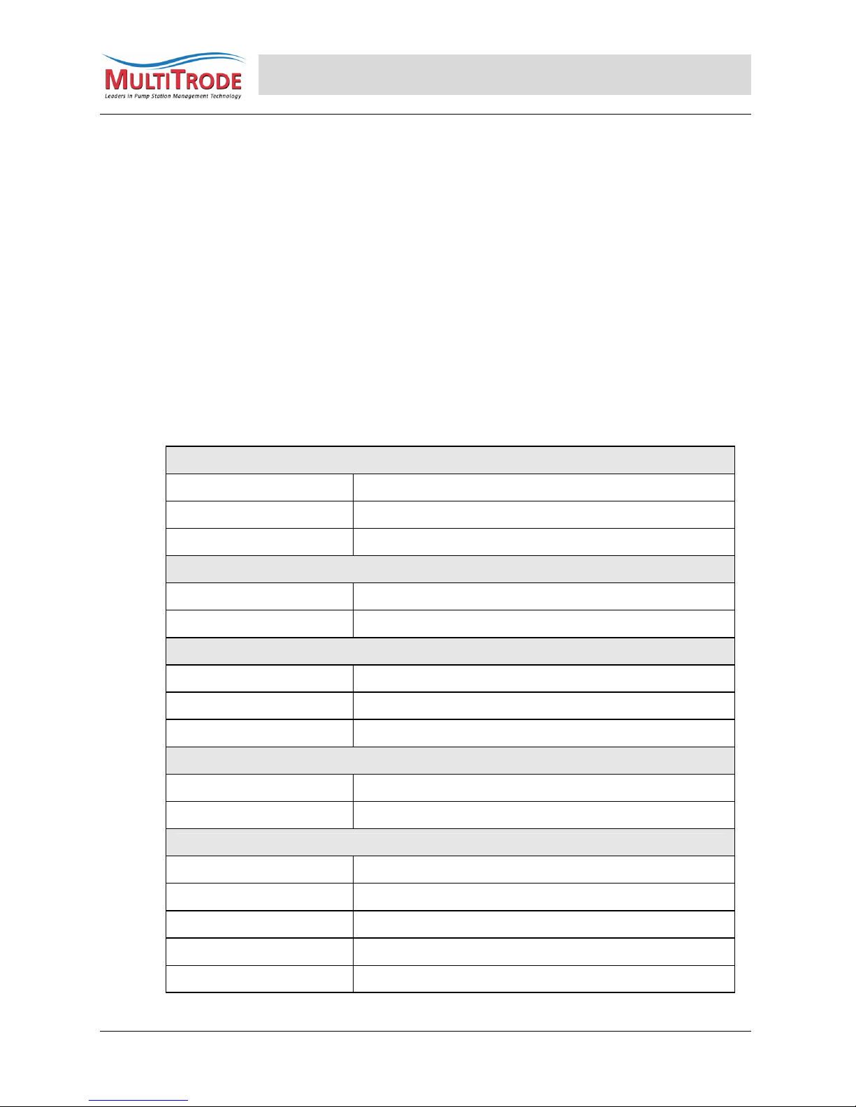
3 Specifications
Dimensions
Width 22.5mm
Height 101mm
Length (depth) 120mm
Environmental
Ambient Temperature -10 to 60 degrees Celsius
Humidity 5% to 95% non-condensing
AC Power Supply
Voltage Range 85 – 265V AC
Frequency 50/60Hz
Power 3.5W
DC Power Supply
Voltage Range 12 – 30V DC
Current 0.15A max
Relay Outputs
Type Form A
Current (Resistive) 5A
Current (Inductive) 2A
Voltage Rating DC 30V DC
Voltage Rating AC 250V AC

MTRA-FSP Installation & Operation Manual
Page 6 of 16 00242600-MTRA-FSP_Manual.doc
4 Installation
The MTRA-FSP is designed to be mounted onto a standard DIN rail. All power
supply, input and output connections are located on the top of the relay
housing.
4.1 Power Supply
The MTRA-FSP can be supplied power in the following ways:
•85 – 240V AC
•85 – 240V AC with 12 – 30V DC Backup
•12 – 30V DC Supply Only
A switch or circuit-breaker and an overcurrent protection device must be
included in the installation. The disconnection device must be in close proximity
to the equipment and within easy reach of the operator, and be marked as the
disconnecting device for the equipment. The input wiring and the switch/circuit-
breaker/overcurrent device must be rated to at least the nominal input voltage
being used. The recommended current ratings are as follows:
Unit Supply
Range
Recommended Switch/Circuit-
Breaker/Overcurrent Protection
Device Rating
Minimum Supply
Wiring Rating
85-180Vac 0.1A 0.1A
180-265Vac 0.05A 0.05A
12-20Vdc 0.3A 0.3A
20-30Vdc 0.15A 0.15A
MTRA-FSP Installation & Operation Manual
00242600-MTRA-FSP_Manual.doc Page 7 of 16
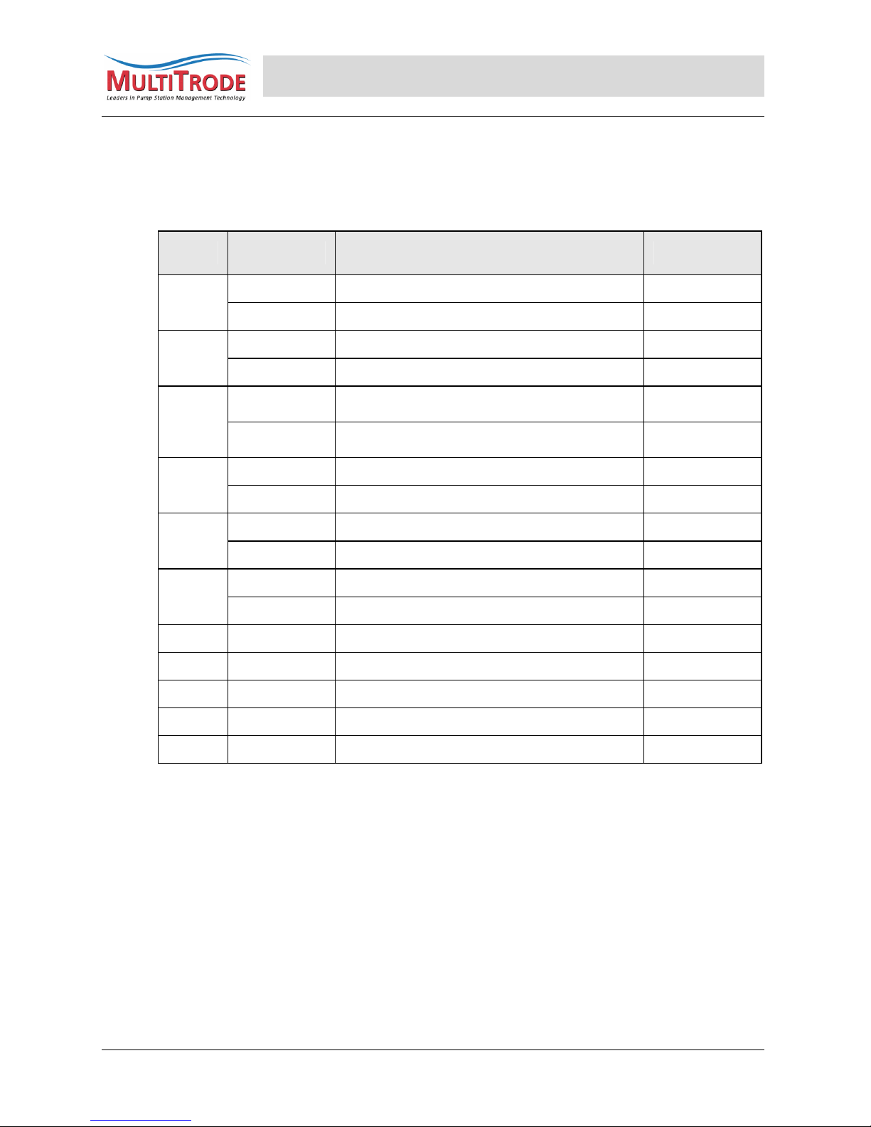
4.2 DIP Switch Settings
The MTRA-FSP is configured using the DIP switches located on the front of the
relay enclosure.
DIP # Setting Mode Description See Section:
OFF Empty (Discharge) Mode 5.1
1 ON Fill (Charge) Mode 5.2
OFF High Level Alarm 6.1
2 ON Low Level Alarm 6.1
OFF 0.5 sec Pump Activation and Deactivation
Delay 8.2
3
ON 10 sec Pump Activation and Deactivation
Delay 8.2
OFF Constant Alarm Output 6.1
4 ON Flash Alarm Output (1Hz) 6.1
OFF 0.5 sec Alarm Activation Delay 8.2
5 ON 10 sec Alarm Activation Delay 8.2
OFF NC Alarm Output 6.1
6 ON NO Alarm Output 6.1
7 8 Probe Sensitivity 8.1
OFF OFF 1kohm
ON OFF 4kohm
OFF ON 20kohm
ON ON 80kohm

MTRA-FSP Installation & Operation Manual
Page 8 of 16 00242600-MTRA-FSP_Manual.doc
5 Operation Modes
The MTRA-FSP can be configured to operate in either Empty (Discharge) or Fill
(Charge) mode.
5.1 Empty (Discharge) Mode
Empty (Discharge) mode is used to pump liquid out of a well once it reaches a
preset level. In this mode the relay operates as follows:
•The pump activates when the liquid reaches the high level probe pump
activation delay period expires.
•The high level alarm probe will operate the Alarm Relay and also the
Pump Relay (in case the high level probe has failed).
•The pump will continue to operate until the liquid level drops below the
low level probe and the pump deactivation period expires.
•A thermal fault will deactivate the pump regardless of liquid level.
•A Probe Failsafe alarm will deactivate the pump regardless of liquid
level.
Note:
Assumed Probe Faults:
If a High Level, or High Alarm input is activated and the Low Level probe
is deactivated, then the relay assumes the Low Level probe is faulty.
In this situation the pump will continue to run for 60 seconds after the
High Level and High Alarm inputs have deactivated. The Probe Fault
LED will turn ON to indicate an Assumed Probe Fault.

MTRA-FSP Installation & Operation Manual
00242600-MTRA-FSP_Manual.doc Page 9 of 16

MTRA-FSP Installation & Operation Manual
Page 10 of 16 00242600-MTRA-FSP_Manual.doc
5.2 Fill (Charge) Mode
Fill (Charge) mode is used to fill up a well with liquid when the level falls to a
preset level. In this mode the relay operates as follows:
•The pump activates when the liquid reaches the low level probe.
•The low level alarm probe will operate the Alarm Relay and also the
Pump Relay (in case the low level probe has failed).
•The pump will continue to operate until the liquid level rises to the high
level probe and the pump deactivation period expires.
•A thermal fault will deactivate the pump regardless of liquid level.
•A Probe Failsafe alarm will deactivate the pump regardless of liquid
level.
Note:
Assumed Probe Faults:
If a High Level, or High Alarm input is activated and the Low Level probe
is deactivated, then the relay assumes the Low Level probe is faulty.
In this situation the relay will wait for 60 seconds after the High Level
input has deactivated, then start the pump. The Probe Fault LED will
turn ON to indicate an Assumed Probe Fault.
Table des matières


