Multitel SDTA-02 Manuel utilisateur
SDTA-02
Step Down Transformer Adapter
User’s Manual

1
PROPRIETARY INFORMATION
The information contained in this document is the property of MULTITEL INC. Except as
specifically authorized in writing by MULTITEL INC., the holder of this document shall:
1. Keep all information contained herein confidential and shall protect same in whole or in
part from disclosure and dissemination to all third parties and
2. Use the same for operating and maintenance purposes only.
© 2001 Multitel Inc.
Printed in Canada 06/2001
Document name:
UMSDTA02012
Issue:
1.2
Revised by:
Eric Boivin
Date:
07/10/11
SDTA-02
Step Down Transformer Adapter
User Manual

2

www.multitel.com [email protected]
3
TABLE OF CONTENTS
CONTROL SHEET ..........................................................................................................4
CONTROL SHEET ..........................................................................................................4
1. GENERAL INFORMATION...................................................................................5
1.1 DESCRIPTION.................................................................................................................... 5
2. SUMMARY OF SPECIFICATIONS........................................................................7
2.1 ELECTRICAL ...................................................................................................................... 7
2.2 ENVIRONMENTAL............................................................................................................. 7
2.3 MECHANICAL .................................................................................................................... 7
3. OPERATION.........................................................................................................8
3.1 GENERAL............................................................................................................................ 8
3.2 ANALOG CHANNEL SETUP ............................................................................................. 8
3.3 MULTITEL MONITORING SYSTEM CONFIGURATION SETUP.................................. 8
4. INSTALLATION...................................................................................................10
4.1 TOOLS AND EQUIPMENT.............................................................................................. 10
4.2 MOUNTING THE SYSTEM.............................................................................................. 10
4.3 WIRING AND CONNECTING.......................................................................................... 11
4.3.1 GENERAL INFORMATION ........................................................................................ 12
4.4 ALERNATIVE VOLTAGE MEASUREMENTS................................................................. 12
5. MAINTENANCE.................................................................................................16
5.1 CALIBRATION .................................................................................................................. 16
5.2 TROUBLESHOOTING...................................................................................................... 16
5.2.1 General......................................................................................................................... 16
FIGURES:
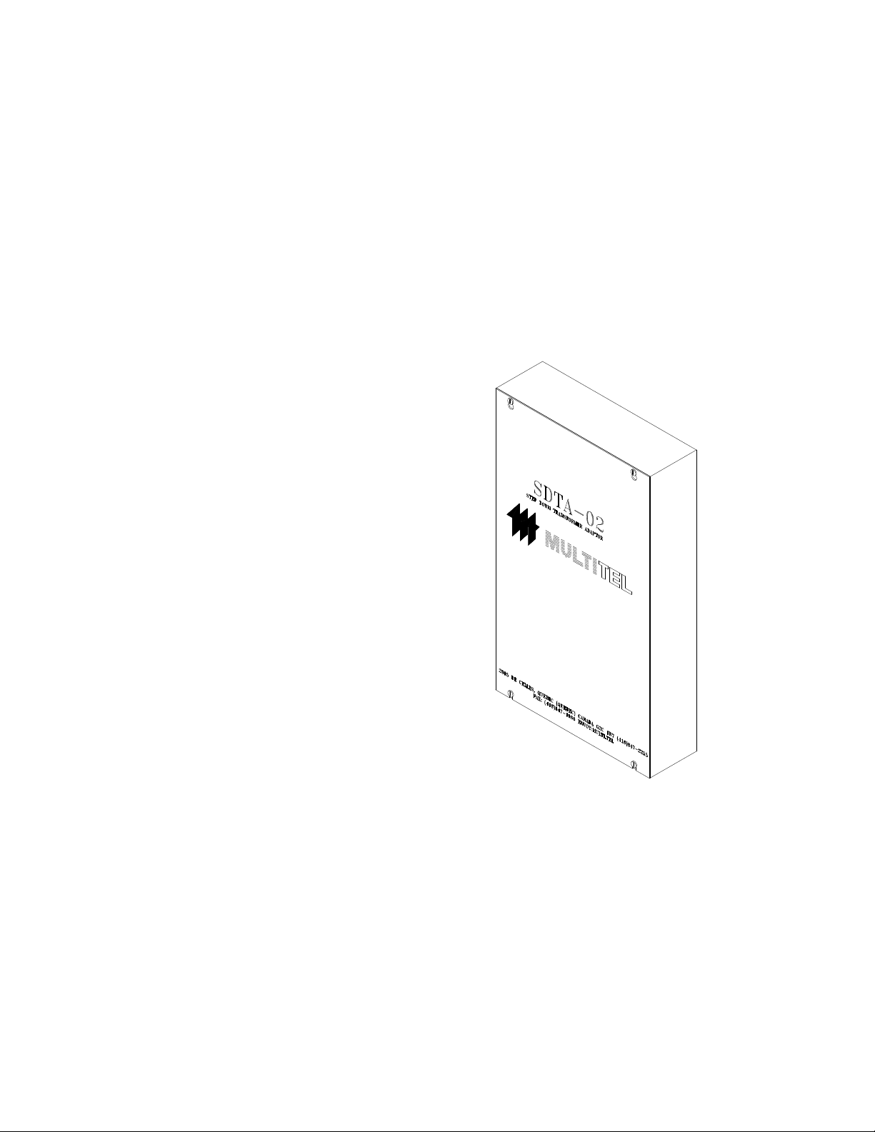
Figure 1 - Physical Aspect.................................................................................................................6
Figure 2 - Wall Mount Installation of the SDTA-02........................................................................11
Figure 3 - AC Current and Voltage Measurements.........................................................................13
Figure 4 - Connector Definitions......................................................................................................14
TABLES:
Table 1 – SDTA-02 Models and Part Numbers...................................................................................5
Table 2 – Current and voltage data for analog channel configuration...............................................8
Table 3 – SDTA-02 Setup ....................................................................................................................9
Table 4 – Diagnosis Path for Troubleshooting .................................................................................17

www.multitel.com [email protected]
4
CONTROL SHEET
ISSUE DATE DESCRIPTION ORIGINATOR
1.0 93/06/25 First English issue. Pierre Poulin
1.01 94/10/12 - -
1.02 97/05/08 Minor modifications and new formatting. François Dionne
1.1 00/06/16 New certification information for CSA-c
and CSA-US
Gilles Belleau
1.12 01/09 Review Johanne Lavallée
Gilles Belleau
1.2 10/07/11 Changer adresse E. Boivin

SDTA-02 GENERAL INFORMATION
www.multitel.com [email protected]
5
1. GENERAL INFORMATION
1.1 DESCRIPTION
The SDTA-02 is an interface accessory that converts AC voltage and current signals into an
AC signal compatible with MULTITEL monitoring systems.
The following list shows the eight possible configurations available for the SDTA-02 interface.
Table 1 – SDTA-02 Models and Part Numbers
DESCRIPTION MULTITEL PART #
SDTA-02, 240 VAC 3 phases M-4173*
SDTA-02, 600 VAC 3 phases M-4178*
*These models are CSA and CSA “US” approved.
For current measurement (0-1000A), current transformers are used to provide the 0-5 Amp
output signal required by the current input interface.
For voltage measurements (0 to 240 VAC and 0 to 600 VAC), three (3) voltage input
interfaces are provided, each with a 2-wire input connection.


SDTA-02 SUMMARY OF SPECIFICATIONS
www.multitel.com [email protected]
7
2. SUMMARY OF SPECIFICATIONS
2.1 ELECTRICAL
Current consumption 150 mA / phase maximum
Current input range 0-5 A AC
Input impedance
Voltmeter 240 V : 2400 Ω
600 V : 6000 Ω
Ammeter 0.2 Ω
Output signal
Voltmeter 17 VAC, 2 nominal inputs (max.
28 VAC)
Ammeter 500 mVAC
2.2 ENVIRONMENTAL
Temperature
Operation 0ºC to 50ºC (32ºF to 122ºF)
Storage -40ºC to 70ºC (-40ºF to 158ºF)
Humidity
Operation 0 to 90%, non-condensing
Storage 0 to 95%, relative humidity
2.3 MECHANICAL
Height 43 cm (17”)
Width 25 cm (10”)
Depth 8 cm (3”)
Weight 3.2 kg (7 lbs)
SDTA-02 OPERATION
www.multitel.com [email protected]
8
3. OPERATION
3.1 GENERAL
The SDTA-02 is designed to transform high-AC currents and voltages into a current or
voltage scale compatible with analog channels on MULTITEL’s monitoring systems,
such as the RPM-1000/C, the MXP2 188 and the MIRADOR.
3.2 ANALOG CHANNEL SETUP
The SDTA-02 will send its measurements to several analog channels on your
MULTITEL monitoring system. In order to operate properly, those analog-input
channels need to be programmed with the proper scaling factor according to the AC
voltage or AC current input range (see Table 2). Please refer to the user’s manual of your
MULTITEL monitoring system for a complete description of steps to follow in order to
configure it accordingly.
Table 2 – Current and voltage data for analog channel configuration
INPUT RANGE SCALE INPUT SOURCE
0-240 VAC
0-600 VAC 565
1400 Voltage
Voltage
3.3 MULTITEL MONITORING SYSTEM CONFIGURATION SETUP
The SDTA-02 has been set in the factory according to your needs. However, you should check
that setting is correct in order to avoid erratic readings (see the following table).

SDTA-02 OPERATION
www.multitel.com [email protected]
9
Table 3 – SDTA-02 Setup
PHASE JUMPER MXP2/MIRADOR RPM 1000/C
Phase A JP5 OFF ON
JP6 ON OFF
JP9 ON OFF
Phase B JP3 OFF ON
JP4 ON OFF
JP8 ON OFF
Phase C JP1 OFF ON
JP2 ON OFF
JP7 ON OFF
Table des matières
Autres manuels Multitel Adaptateur


