TABLE OF CONTENTS
CONTROL SHEET ............................................... 4
1. General Information............................................ 5
1.1 Description .................................................................................................... 5
1.2 Content .........................................................................................................6
2. Specifications..................................................... 7
2.1 Electrical Specifications.................................................................................. 7
2.2 Environmental Specifications.........................................................................7
2.3 Mechanical Specifications..............................................................................7
3. Operation ......................................................... 8
3.1 General.......................................................................................................... 8
3.2 Analog Channel Setup ...................................................................................8
4. Installation........................................................ 9
4.1 Tools and Equipment..................................................................................... 9
4.2 Mounting the System.....................................................................................9
4.3 Cables and Connections............................................................................... 10
4.3.1 General Information ..................................................................11
4.3.2 Connecting the Primary to 110 VAC ..........................................11
4.3.3 Connecting the Primary to 220 VAC ..........................................12
4.3.4 Connecting the Secondary Circuit ..............................................14
4.3.5 Definition of Connectors ............................................................14
5. Maintenance..................................................... 15
5.1 Calibration................................................................................................... 15
5.1.1 Mirador or Site Manager............................................................15
5.1.2 MXP2 188..................................................................................15
5.2 Troubleshooting........................................................................................... 16
6. Contacting Multitel............................................ 18
Index ................................................................. 19
TABLES:
Table 1 - Configuration of the analog channel ...................................................... 8
Table 2 – Wiring of the primary for 110 VCA..................................................... 11
Table 3 – Wiring of the primary for 220 VCA..................................................... 13
Table 4 – Wiring of the secondary circuit to the SDTA-01 .................................. 14
Table 5 - Definition of J3 ................................................................................... 14
Table 6 - Definition of J8 ................................................................................... 14
FIGURES:
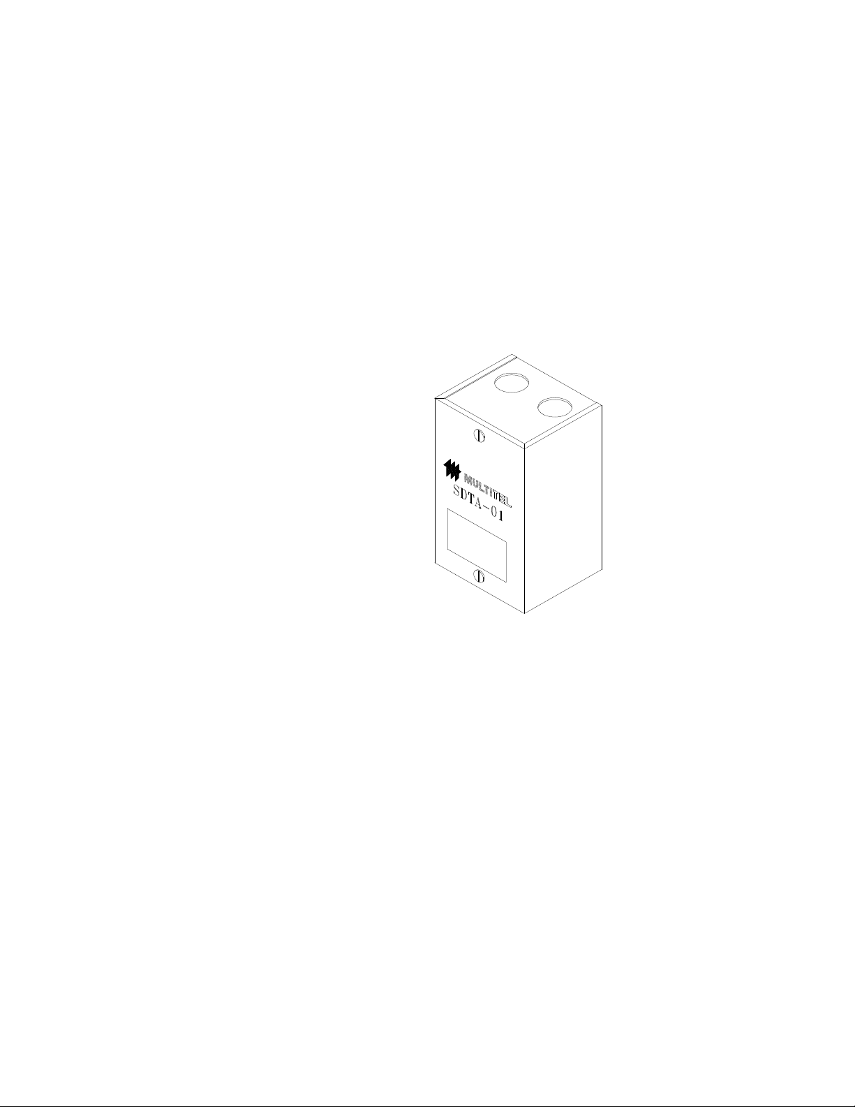
Figure 1 - Physical appearance of the SDTA-01.................................................... 5
Figure 2 Wall installation of the SDTA-01 ......................................................... 10
Figure 3 Connecting 110 VCA to the SDTA-01 ................................................. 12
Figure 4 Connecting 220 VCA to the SDTA-01 ................................................. 13
3