Motomaster 009-1534-6 Manuel utilisateur

HYDRAULIC
ATV AND LAWN MOWER JACK
INSTRUCTION
MANUAL
model no. 009-1534-6
IMPORTANT:
Please read this manual carefully before operating this jack and
save it for reference.
300 LB (136 KG) Maximum Weight
INTRODUCTION
2
IF ANY PARTS ARE MISSING OR DAMAGED, OR IF YOU HAVE ANY
QUESTIONS, PLEASE CALL OUR TOLL-FREE HELPLINE AT
1-888-942-6686
model no. 009-1534-6 I contact us 1-888-942-6686

TABLE OF CONTENTS
3
TABLE OF CONTENTS
Safety
Specifications
Important safety information
Assembly
Bleeding
Lifting
Cleaning, maintenance, and lubrication
Troubleshooting
Lowering
Maintenance
Exploded view
Operation
4
4
4
6
12
Key parts diagram 11
12
12
13
14
14
15
16
Parts list 17
Environmental concerns 18
Warranty 18
SAVE THESE INSTRUCTIONS
This manual contains important safety and operating instructions. Read all instructions and follow
them while using this product.

SAFETY
4
IMPORTANT SAFETY INFORMATION
SPECIFICATIONS
Rated Capacity Maximum Lift Height
300 lb (136 kg) 23 13 / 16" (60.5 cm)
Axle Width
36 – 50 1/2" (91.4 – 128.3 cm)
Assembly Precautions
Failure to heed these warnings may result in personal injury and/or property damage.
• Assemble only according to these instructions. Improper assembly can create
hazards.
• Wear ANSI-approved safety goggles and heavy-duty work gloves during assembly.
• Keep assembly area clean and well lit.
Use Precautions
• Study, understand, and follow all instructions before operating this device.
• Do not exceed rated capacity.
• Use only on hard, level surfaces.
• Load wheels equally.
• Lift only on areas of the vehicle as specified by the vehicle manufacturer.
• Immediately after lifting load, ensure jack mechanical load holding means is engaged.
• Do not move while loaded.
• Secure load with appropriate restraint device.
• Do not adjust safety valve.
• Wear ANSI-approved safety goggles and heavy-duty work gloves during use.
• Keep clear of load while lifting and lowering.
• Lower load slowly.
• Do not use for aircraft purposes.
• Inspect before every use; do not use if parts loose or damaged.
• Keep your work area clean and well lit. Cluttered work areas invite accidents.
• Do not allow anyone on the vehicle while using the jack. Keep bystanders a safe
distance away from the vehicle and jack.
• Stay alert. Watch what you are doing, and use common sense when operating a jack.
Do not use a jack while tired or under the influence of drugs, alcohol, or medication. A
moment of inattention while operating jacks may result in serious personal injury.
model no. 009-1534-6 I contact us 1-888-942-6686

SAFETY
5
• Store idle jacks out of reach of children and other untrained persons. Jacks are
dangerous in the hands of untrained users.
• Jack service must be performed only by qualified repair personnel. Service or
maintenance performed by unqualified personnel could result in a risk of injury.
• When servicing a jack, use only identical replacement parts. Follow instructions in the
“Maintenance and Servicing” section of this manual. Use of unauthorized parts or
failure to follow maintenance instructions may create a risk of injury.
• Before use, read manufacturer's instruction manual for the vehicle you will lift.
• Do not support both ends of the vehicle at the same time.
• Before lowering the jack, remove all tools and equipment from under the vehicle.
• The warnings, precautions, and instructions discussed in this manual cannot cover all
possible conditions and situations that may occur. The operator must understand that
common sense and caution are factors which cannot be built into this product but
must be supplied by the operator.
SAVE THESE INSTRUCTIONS.
Failure to heed these markings may result in personal
injury and/or property damage.

ASSEMBLY
1
2
WARNING!
Read the ENTIRE IMPORTANT SAFETY INFORMATION section at the beginning of this manual
including all text under subheadings therein before set up or use of this product.
6
model no. 009-1534-6 I contact us 1-888-942-6686
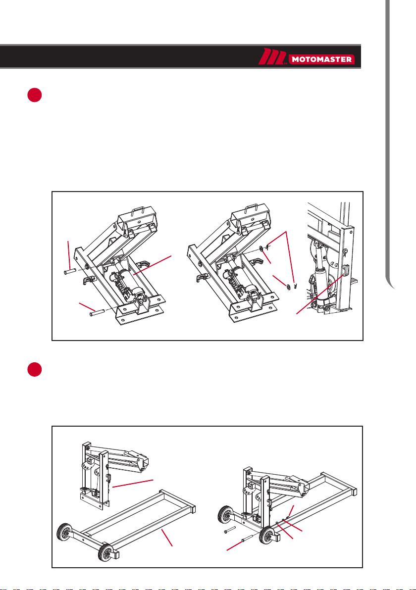
Put Shaft (11) and Lift Arm Assembly (23) shown in Fig. a.
Connect the pins on the Shaft (11) through the holes on Upper Lift Arm (27)
shown in Fig.b.
Slide Lift Arm Pin (18) through Shaft (11) and Lift Arm Assembly (23) shown
in Fig. c & d.
Fig. a Fig. b Fig. c Fig. d
ASSEMBLY INSTRUCTIONS
Place Lift Arm / Shaft Assembly flat on a horizontal surface.
Move the two Safety Lock Levers (14) to the unlocked position as shown in Fib. b.
Raise the Lift Arm portion of the assembly to the position shown in Fig. c.
Prepare Lift Arm / Shaft Assembly
Lift Arm / Shaft
Assembly
Lift Arm
Safety Lock
Lever (14)
Safety Lock
Lever (14)
Lift Arm
Assembly (23)
Upper Lift Arm
Lift Arm Pin (18)
Shaft (11)
Fig. a Fig. b Fig. c
(27)
7
ASSEMBLY
3
4
Fig. a
Install Ram
Upper Ram
Pin (22)
Lower Ram
Pin (7)
Ram (19)
R- Clip (6)
Safety Lock Lever (14)
Fig. b Fig. c
Lift Arm/Shaft
Aeembly
Base (1) Bolt (10)
Lock
Washer (9)
Washer (17)
Nut (8)
Position the Ram in Lift Arm I Shaft Assembly as shown.
Press the pump piston rod to the proper position with the foot pedal and install it as
shown in the figure.
Slide Lower Ram Pin (7) through the shaft bracket and the clevis base of the Ram (19).
Slide Upper Ram Pin (22) through the bracket on the Lift Arm and the top of the Ram (19).
Place Washer (17) over the end of each Pin.
Secure each Pin with an R-Clip (6).
Move the two Safety Lock Levers (14) to locked position as shown in Fig.c.
Place the Lift Arm I Shaft Assembly onto the wheeled end of the Base (1 )
as shown and align the bolt holes.
Secure the Lift Arm I Shaft Assembly to the Base using two Bolts (10), Washer (17)
Lock Washers (9), and Nuts (8).
Connect Lift Arm / Shaft Assembly to Base
Washer (17)
5
6
ASSEMBLY
Extension Beam Pin (32)
Extension Beam (31)
Washer (17)
R-Clip (6)
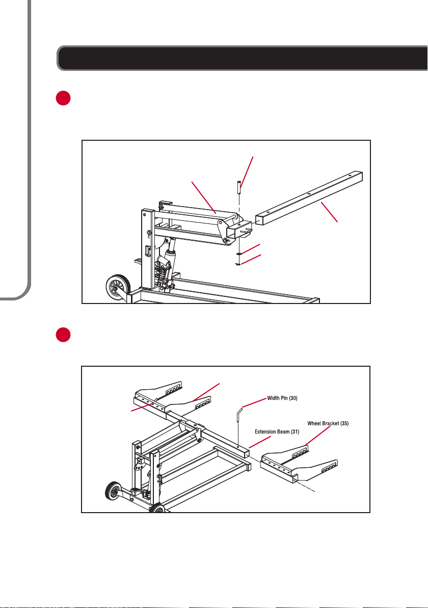
Insert Extension Beam (31) through the bracket on the Upper Lift Arm (27).
Insert Extension Beam Pin (32) through centre of bracket.
Hold Washer (17) over end of Extension Beam Pin and secure it with R-Clip (6).
Attach Extension Beam
Install Wheel Brackets
Slide one Wheel Bracket (35) over each end of the Extension Beam (31).
Insert Width Pins (30) to secure them in place.
Width Pin (30)
Wheel Bracket (35)
Upper Lift Arm (27)
8
model no. 009-1534-6 I contact us 1-888-942-6686
ASSEMBLY
9
7
8
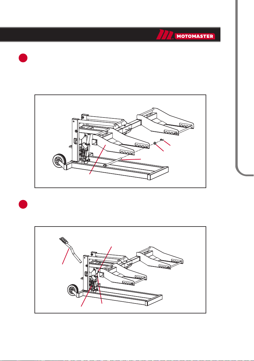
Remove the R-Clip (6) and Washer (33) from one end of each Wheel Bracket
Rod (34).
Insert one Wheel Bracket Rod through the slots on each Wheel Bracket (35).
Replace the Washer over the end of each Wheel Bracket Rod and
use an R-Clip to secure the end of each Rod in place.
Insert the Foot Pedal (21) into its holder on the Ram (19).
Secure the Foot Pedal in place using the Lock Washer (36) and Foot Pedal
Bolt (20) through the side of its holder.
Attach Wheel Bracket Rods
Install Foot Pedal
Foot Pedal Bolt (20)
Foot Pedal (21)
Ram (19) Lock Washer (36)
Wheel Bracket (35)
Wheel Bracket Rod (34)
Washer (33)
R-Clip (6)
ASSEMBLY
10
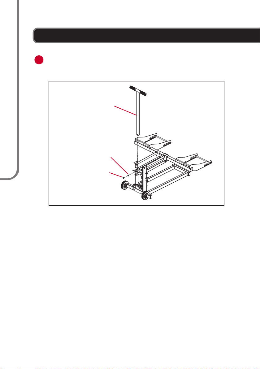
9Insert the Handle (25) into the bracket on the Lift Arm I Shaft Assembly and
align the holes.
Secure in place using the Handle Bolt (12) and Lock Washer (9).
Install Handle
Handle (25)
Lock Washer (9)
Handle Bolt (12)
model no. 009-1534-6 I contact us 1-888-942-6686
Table des matières
Langues :
Autres manuels Motomaster Jack


Manuels Jack populaires d'autres marques


VEVOR
VEVOR TJD-12000SP-F Manuel utilisateur

ULTIMATE SPEED
ULTIMATE SPEED URW 2 A1 HYDRAULIC TROLLEY JACK Manuel utilisateur

Stels
Stels 51131 Manuel utilisateur

Bushranger
Bushranger RJX01 Manuel utilisateur

Clarke
Clarke CTJ2500QLG Manuel d'installation et d'exploitation

Valex
Valex 1650520 Manuel utilisateur


