MORLEY M48 Manuel utilisateur

ORLEY
EQUIPMENT CO
M48
HYUNDAI
OWNERS
MANUAL
SERIAL #:
ENGINE #:

WARNING
• Ifoperatedimproperly,thismachinemaycauseseriousinjury.
• Donotwearlooseclothingwhenoperatingthismachineasitmay
becomeentangledintheequipment.
• Stayclearofallmovingpartswhenthemachineisrunning.
• DONOTworkonthismachinewhiletheengineisrunningandNOT
properlysecured.
• ALWAYSwearsafetyglasses,soundprotection(earplugs),hand
protection(gloves),andsteel-toedbootswhenoperatingthismachine.
• NEVERstandinwaterwhileoperatingthismachine(ELECTRIC
MODEL).
• ALWAYSuseproperlygroundedpowercords(ELECTRICMODEL).
• PowercordsshouldALWAYSbetheproperwiregaugeforeach
particularapplication(ELECTRICMODEL).
• ALLextensioncordsshouldbepluggedintoa“groundfault
interrupter”(ELECTRICMODEL).
• NEVERuseextensioncordsthatareinanywaydamaged,frayedor
cut(ELECTRICMODEL).
• ALWAYSusethepropercuttingRPMasspecificiedbyyourblade
manufacturer.
• ALWAYSshutoffthemachinebeforechangingtheblade(UNPLUG
ELECTRICMODELbeforechangingtheblade).
• InsureproperpositionandsecurityofALLsafetyguardsbefore
operatingthismachine.
• ALWAYSinspectthemachinebeforeuseforsafeoperation.
• FIREHAZARD!Inspectforanyleakingfluids(gas,oilandetc.)
operationofthismachine

• DONOTattemptofoff-loadanypieceofequipmentonunevengroundof
anydegreeofslope.DONOTleaveequipmentunattendedonuneven
ground.Injuryordeathmayoccur.
THIS EQUIPMENT SHOULD NOT BE OPERATED BY ANYONE UNDER
THE AGE OF 18.
• DONOTjump-startadeadbatteryonthismachine.Theprocessof
jump-startingadischarged(dead)batterycan,undercertainconditions,result
inabatteryexplosionfromtheignitionofhydrogengas,resultingininjury
ordeath.
WARNING Continued
WARRANTY:
MorleyEquipmentCompanyWarrantsthatatthetimeofshipment,theproduct
manufacturedbyMorleyEquipmentCompanyandsoldhereundershallbefreefrom
defectsinmaterialandworkmanship.
WARRANTY ADJUSTMENTS:
MorleyEquipmentCompanyagreestorepairorfurnishanyfaultycomponentwithin30-
daysfromdateofpurchaseprovidedthemachineisoperatedandmaintainedin
accordancewithMorleyEquipmentCompanyOwnersandEngineManualsand
OperatingInstructions.
IfexaminationsbyMorleyEquipmentCompanyprovesadefectwithinWarranty,receipt
verifyingpurchasedateandserialnumbersarerequiredtoobtainAdjustment.Oneyear
Warrantyonmajorcomponents(suchasengine,drivemotors,hydraulicpump,
hydraulicmotorandetc.)withanauthorizedservicefacility.SeeOwnersManualfor
Warrantyfromthemanufacturerofthatproduct.
Noproductwillbeacceptedforreturnorreplacementwithoutpriorauthorizationby
MorleyEquipmentCompany.Productsreturnedareaddressedto:
Morley Equipment Company, 41161 Sandalwood Circle, Murrieta, CA 92562:
(951) 894-5558.
EXCLUSIONS FROM WARRANTY:
ThisWarrantydoesnotextendtoanyproductsuppliedbyMorleyEquipmentCompany
whichhasbeensubjectedtomisuse,neglect,accident,improperinstallationorusedin
violationofinstructionsprovidedbyMorleyEquipmentCompany.
LIMITED WARRANTY

M48 SAW INFORMATION
1. ThisManualprovidesthebasicinstructionsfortheoperationandmaintenanceof
theM48concretesaw.AndEngineManualisalsoprovidewitheachsaw.
2. M48 - WATERCOOLED:
ENGINE: Hyundai ZPP 416 - Gas
Drive Unit: Hydrostatic Transmission
Water Pump: Self-priming Electric (Optional)
Spindle: 1-7/16”
Arbor Size: 1” with 1/4” Keys
Blade Capacity: 14” to 36” Diameter
Depth Control: Hydraulic Raise/Lower
Depth Gauge and Locking Stop
Fuel Capacity: 5-Gallons
Weight: Single Speed: 1,040 Lbs, 3-Speed: 1,130 Lbs
Length: 43”
Width: 29” w/Quick Detach Spindle
Height: 44”
OPTIONAL EQUIPMENT
1. 3-Speed Gearbox
2. Night Light
3. Bladeguards - 24”, 30”, and 36”
4. Electric Water Pump
3. Thenewmachinewastest-runbeforeleavingMorleyEquipmentCompany,
however,theengineshouldbecheckedwiththeEngineManualsothatthe
correctroutineisfollowedatalltimes.Checkallfluidlevels.Thisisvery
importantduringtheinitialrunning-inoftheengineasspecifiedintheEngine
Manual.
4. LUBRICATION/SERVICE CHART
ITEM
HydrostaticTransmission(F/R)
AirFilter
HydraulicPump(R/L)
SpindleBearings
PivotAxle
FrontWheels
Radiator
CHECK
Monthly
Weekly
Monthly
Daily
Weekly
Weekly
Daily
LUBRICANT
20W-50MotorOil
Serviceasrequired
ATF
Grease
Grease
Grease
Squirtdebrisoutof
coolingfins

5. Toadjustorreplacethebelts,loosenthe1/2”“pinch”bolts,oneoneitherside
atthefrontofthemotorbaseplate,andthetwo5/8-inchboltsthatrunverticalatthe
frontotthemotorplate.Thisallowsthemotortoberaisedorlowered,looseningthe
beltsforreplacementortensioning.Thenraisethemotorandtightenthebolts
afterbeltreplacementortoadjusttension.Itisimportantthatthetensionisjust
enoughtodrivewithoutslipping.Tootightshortensbearinglife,toolooseshortens
beltlife(SpindleshaftBelts-(7)3VX400,SingleSpeed&3-Speed.)
CONTROL OPERATING INSTRUCTIONS
1. WATER SUPPLY: Connectthewatersupplytothe“inlethose(1/2”),”openthe
watervalveandmakesurethat“outlet(1/4”),”hosesmountedinthe
bladeguardarefreeofobstructions.Blowoutthewaterlinesbeforeoperationin
freezingconditions.
2. RAISE/LOWER: BypullingbacktheRaise/Lowerleveramomemtaryswitch
activatesanelectric-over-hydraulicpumptoraisethesaw.Pushtheleverfowardto
lowerthesaw.Youcancontroltheloweringspeedbyopeningthevalvegradually.
Foradjustingthehandleassembly,seeaccompanyinginstruction.
3. SPEED CONTROL: TheForward/Reverseleverdeterminesforwardandreverse
speeds,witha“neutral”dynamicbrakepositioninbetween.Bypushingthespeed
controlleverfoward,thesawwillmoveforwardatvariablespeeds,pullingthelever
backdoesthesameinreverse.
4. BLADE FITTING: Raisethesawtoaccommodateyourchoiceofblades-14”to30”.
Liftoffthebladeguardwithengineoff.Removethespindlenutwiththespindlenut
wrenchprovidewiththesawandthentheouterbladecollar.Inspectbothcollarsso
theywillseatflushwiththeblade.Placebladeonspindleshaftandalignwithcollarpinin
innercollar,nowreplaceoutercollarandspindlenut-tightenbystrikingspindlenutwrench
withprovidedhammerandfinally,replacebladeguard.
5. STARTING THE ENGINE: ThisshouldbedoneasexplainedintheEngine
Manual.
6. POSITIONING THE SAW: Thesawmaybemaneuveredinseveralways.Position
thehandlebarstosuittheoperator’sleverage(Note:thisisarear-pivotsaw).The
independentdrivemotors,thefunctionasadifferential,allowthesawtoberotatedby
liftingthefrontwheelsoffthegroundbypushingdownonthehandlebarsandrotating

7. CUTTING: Layoutthecutsusingachalklineorstringandpaint.Usethe
pointerguideasyousawcut“gunsite.”Bringtheenginetotheblademanufacturer’s
recommendedRPM.Positionthesawtoinitiatethecut.Whenalignedandpositioned,
turn-onthewaterandlowerthesawtodesiredcutdepth,thenmovethesawforwardto
acomfortablecuttingspeed-don’t“labor”theblade.Wateramountisanacquired
science-askyourblademanufacturerforrecommedantions.Readingtheslurryisyour
keytocost-effectivecutting-justtherightamountofwaterisneededforcuttingspeed
andbladelife(ablade’saccumulatedinch-feetcut).Itisrecommendedtostep-cut-
takeseveralpassestoreachdesireddepth-thisalsobenefitsbladelife.Oncethe
chalked-outcuthasbeencompleted,returntheForward/Reverselevertothe“neutral”
positionandusingtheRaise/Lowerlever,raisethesawoutofthecut.Ifstep-cutting,
returnthesawtotheoriginalinsertionpointandlowerthebladetothesecondarydepth
andrepeatthecut,thenraisethebladeasbeforeandpositionthesawforthenextcut.
8. CLEANING: Theentiresawshouldbethoroughlywashedweeklyorasrequired.
Usecautiontopreventwaterfromassociationwiththefueltandandelectricalsystem.
WD40workswellasawaterdispersant.Besuretosquirtanydebris-dust,slurry
andetc.-outoftheradiator’scoolingfins.
9. STORAGE: Alwayslubricatethesawaftercleaning.
10. CALIBRATION: Alwayscheckalignment.Thespindleshaftandrearaxlesmustbe
alignedtoinsurethesawtravelsstraightandtheblademovesparalleltotherear
wheels.
11. REPLACEMENT PARTS: Allreplacementpartsmustbeorderedfrom
MorleyEquipmentCompanytoeffectWarranty.AlwayssupplyModelandSerial
Numberwhenorderingparts.
12. QUESTIONS AND CONCERNS: Shouldyouhaveanyquestionsrelativetothe
operationorservicingyourequipment,donothesitatetocontactMorley Equipment
forthesawisalsoavailableon-lineatwww.morleysaws.com
CONTROL OPERATING INSTRUCTIONS Continued:
thesawontherearwheelsinthedesireddirection,leftorright,andpositioningforthe
nextcut.Thesawmayalsobepositionedbyusingthe“wheel-borrow”approach-lift
therearwheelsandrotatetothedesiredpositionusingthefrontwheelstopivotthe
saw.

M48 PARTS LIST
SPINDLESHAFT ASSEMBLY
PARTS# REQUIRED DESCRIPTION
1100-48 1
1101-48 2
1115-48 2
1116-48 2
1104-48 1
1105-48 1
1106-48 1
1107-48 1
1108-48 1
1109-48 2
1110-48 6
1118-48 1
1119-48 1
Spindleshaft
Pillow-blocking Bearing
Inner Collar
Outer Collar
Left-hand Nut
Right-hand Nut
Sheave
Bushing
Key - 3/8”
Key - 1/4”
3VX 425 Belt
L-hand Spindle Stud
R-hand Spindle Stud
2100-48 1 Weldment
2112-48 2 Axle - 1”
3002-48 2 Wheel - 6x2”
5004-48 2 Collar - 1”
2104-48 2 Pillow-block Bearing - 1”
2105-48 1 Pin - 5/8”x3.5”
2106-48 1 Depth Gauge, Cable, and Spring
2114-48 1 Pin - 5/8”x3”
3100-48 1
3101-48 1
3102-48 1
3103-48 1
3106-48 1
Pump Motor
Flow Control Valve
Hydraulic Cylinder
Raise/Lower Assembly
Solenoid
FRONT AXLE ASSEMBLY
HYDRAULIC RAISE/LOWER ASSEMBLY

HYDROSTATIC DRIVE ASSEMBLY
PART# REQUIRED DESCRIPTION
4100-48 1
4101-48 2
4102-48 1
4103-48 2
3001-48 2
4105-48 1
4106-48 1
4107-48 1
4201-48 1
4109-48 1
4110-48 2
4111-48 1
4112-48 1
4113-48 1
Pump
Drive Motor
Traction Manifold
Wheel Hub
Wheel - 10”x3”
Filter Assembly
Filter
Reservoir - Plastic
Forward/Reverse
Lever Assembly
Cable
Drive Cable 33"
Hydrostatic Pump Belt – 4L3400 or A-32
Wheel Motor Bracket
Hydrostatic Drive Pump Bracket
5100-48 1
5101-48 1
5102-48 2
5103-48 2
5104-48 1
Weldment
3”
Pointer Wheel
Delrin Bushing
Cable
Lift Cable
6100-48 1
6101-48 1
6102-48 1
6103-48 1
6105-48 1
6106-48 1
6107-48 1
3022-48 1
3026-48 2
6110-48 2
6118-48 1
2111-48 1
2119-48 1
Mainframe
Console
Belt Guard - Left Side
Belt Guard - Right Side
Air Intake - Rear
Air Exhaust - Left Side
Access Panel - Electrical
Handlebar
Locking T - Handle
Fuel Tank
Gas Cap
Lower
Depth Stop Rod
Assembly
Upper
Depth Stop
Rod
Assembly
POINTER ASSEMBLY
FRAME CONSOLE

FRAME CONSOLE Continued:
PART# REQUIRED DESCRIPTION
6115-48 2 Fuel Tank Hold-down Strap
HYUN-48 1
7101-48 2
7102-48 1
7102-48-A 2
7102-48-B 1
7102-D 1
7102-E-M48 1
7103-48 1
7104-48 2
4183-48 2
7106-48 1
7107-48 1
7108-48 1
7109-48 1
7124-48 1
6117-48 1
6114-48 1
Hyundai 1.6-Liter, Gas
Bellhousing - Inner/Outer
Output Shaft/Drive Assembly
Bearing - Output/Drive Assembly
Shaft - Output/Drive Assembly
BoWex Male Coupler
BoWex Female Coupler
Air Filter
Air Filter Element
Hose - 90-Degree Elbow - 2”
Hose Coupler
Air Filter Bracket
Exhaust/Catalytic Converter
Exhaust/Catalytic Converter Bracket
Fuel Pressure Regulator
Fuel Pump
Fuel Filter
8100-48 1 Water Distribution Block w/Hose Fittings
8181-48 2 Outlet Water Hose - 1/4”
8102-48 1 Inlet Water Hose - 1/2”
8103-48 1 Water Valve
8104-48 1 Mud Flap
8105-48 1 20” Bladeguard
8106-48 1 26” Bladeguard
8107-48 1 30” Bladeguard
8108-48 1 36” Bladeguard
ENGINE
BLADEGUARD ASSEMBLY
7711-48 1Radiator
3009-48 1 Fan Stroud
7774-48 1 Electric Fan
7719-48 1 Fan Relay Harness
COOLING SYSTEM
CONSOLE
PART# REQUIRED DESCRIPTION
9100-48 1 Tach/Engine Vitals Gauge
9101-48 1 Emergency Shutoff Switch
9102-48 1 Push-Bottom Start Switch
9103-48 1 Engine Speed Control Switch
9104-48 1 Engine Service Indicator Light
9105-48 1 Upper Console Sticker
9106-48 1 Lower Console Sticker
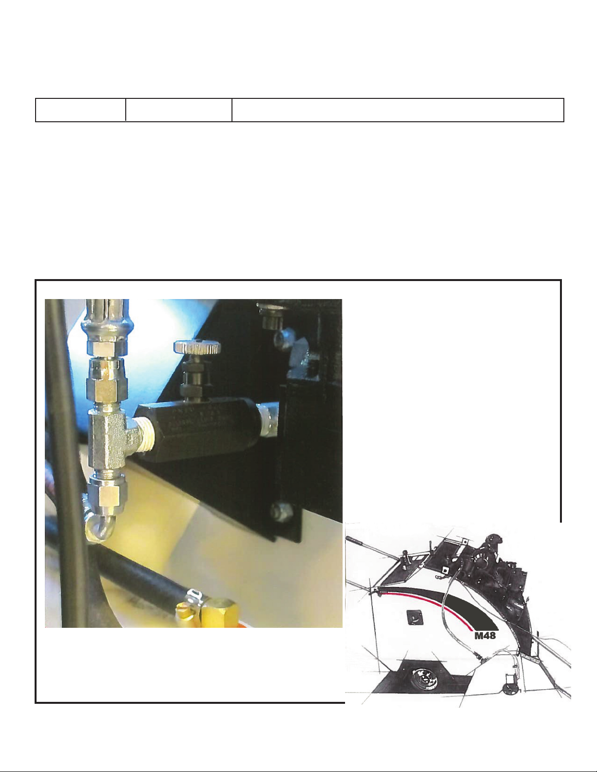
RAISE
FLOW CONTROL
VALVE
Justinsidetherearaccess
panelontherightsideisa
needlevalvethatallowsyouto
adjustthraisingspeed
impartedbytheRaise/Lower
Lever.Yoursawcomeswiththe
raisespeedpre-setatthe
factory.Thisvalveallowsyouto
resetthespeedtosuityour
needs
Table des matières
Autres manuels MORLEY Équipement industriel


