Morbark 20 Manuel utilisateur

Operator’s Manual
Morbark Integrated Control System
Model 20 Chipper


Contents
Introduction iv
Parts Identification 6
Display Module Display Pages 9
Main Page 11
Engine Information Page 12
Feed Control Page 13
Control Devices Page 14
Performance Adjustment Pages 15
AutoFeed Settings Page 17
Control Select Page 18
Menu System 19
Accessing the Menu 21
Sub-Menus 23
Adjust Menu 25
Measure 26
Preferences 27
Info 28
Troubleshooting 31

Introduction
Operator’s Manual, Morbark Integrated Control System—Model 20 Chipper
iv
Introduction
This manual was designed to provide a better understanding of the Control Panel that
comes installed on your Machine. Each page of the Display Module, as well as any
adjustable values, will be described in detail.
Contained within:
Part Identification of:1.
Display Pages2.
Display Module Menu System3.
Parameter Adjustments4.
Troubleshooting5.
Each “Display Page” is shown exactly as it is on the Machine. This should make it
easier to follow along when troubleshooting issues in the field. Also, every page has a
section describing what each button on the Display Module does and the corresponding
page number for that specific function.
Control Panel•
Display Module•

Operator’s Manual, Morbark Integrated Control System—Model 20 Chipper v
Cautions and Warnings
Warning: Before welding on the Machine, ensure that
all connectors are disconnected from the control panel.
Failure to do so could result in damage to the panel itself
or its components.
Warning: Disconnect all power before making any wiring
connections to the control panel.
Caution: Improper operation of these controls could cause
damage to equipment. Do not allow anyone to operate
this equipment before completely reading the manual.
Caution: Electronic controls are intended as general pur-
pose switches. They are not safety devices. Malfunctions
may occur.
Caution: Electronic products are used to initiate an
operation where false operation could be dangerous.
Point-of-operation guarding devices must be installed and
maintained to meet OSHA and ANSI Machine safety stan-
dards. The manufacturer shall not accept responsibility for
installation, application, or safety of systems

Parts Identification
Operator’s Manual, Morbark Integrated Control System—Model 20 Chipper
6
Parts Identification
This section describes all connectors and switches located on the exterior of the control
panel, valve driver and the Display Module.
Control Panel Front View
Control Panel Right ViewControl Panel Left View
1
2
8
9
10
11
12
7
6
5
4
3

Operator’s Manual, Morbark Integrated Control System—Model 20 Chipper 7
Parts Identification
Panel / Valve Driver Parts Identication
No. Description
1Master Display Module
2Manual Controls / Keypad
Feed Forward — Engage the Feed System•
Feed Reverse — Reverse the Feed System•
Yoke Up — Raise the Yoke•
Yoke Down — Lower the Yoke•
Spout Left — Rotate the Spout Left•
Spout Right — Rotate the Spout Right•
Throttle Increase — Increase the speed of the Engine•
Throttle Decrease —Decrease the speed of the Engine•
3Diagnostics Connector
4Tether — Connection Point for the Tether control
5Cat Data Link
6John Deere or Cummins Data Link
7Key Switch
8Modem Option Connector
9Battery connector — To “Main Disconnect” and Negative (-) post on Starter
10 Engine Connector — Connects to the Engine on the Machine
11 Input Harness Connector
Hood Switch•
Feed Stop•
Feed Bar Proximity Switch•
Fuel Gauge•
12 Output Harness connector
Feed Forward•
Feed Reverse•
Yoke Up•
Yoke Down•
Right Track Forward•
Right Track Reverse•
Left Track Forward•
Left Track Reverse•
Spout Left•
Spout Right•
Winch In•
Winch Out•
Track Drive High•
Track Drive Enable•
Fan Reverse•

Parts Identification
Operator’s Manual, Morbark Integrated Control System—Model 20 Chipper
8
Display Module Parts Identication
No. Description
1 “Up” button — This button is used to navigate through the following:
Display Pages•
Menus•
Lists (i.e. selecting “Grinding Mode” or other adjustable parameters)•
2 “OK” button — This button is used as follows:
To navigate to the “Main Page” from any “Display Page”•
To confirm a selection within an adjustable screen (i.e. to set the “Grinding Mode”)•
3 “Down” button — This button is used to navigate through the following:
Display Pages•
Menus•
Lists (i.e. selecting “Grinding Mode” or other adjustable parameters)•
4 “Menu” button — This button is used to access the “System Menu”. It can be used at any time.
5 “Escape button — This button can be used as follows:
To cancel a selection•
Navigate to the “Main Page” from within any “Display Page”•
Escape from the “System Menu” to the “Display Page” that was being viewed prior to enter-•
ing the “System Menu”
6 “Function” buttons — These buttons can be used from within any page in the system. Their
functionality is dependant on the page that is currently displayed. A more in-depth descrip-
tion will be given on a per-page basis.
7 Display Screen
1
2
3
4
5
7
6

Operator’s Manual, Morbark Integrated Control System—Model 20 Chipper 9
Display Module Display Pages
Main Page 11
Engine Information Page 12
Feed Control Page 13
Control Devices Page 14

Display Module Display Pages
Operator’s Manual, Morbark Integrated Control System—Model 20 Chipper
10
Introduction
This section covers the main “Display Pages”. A listing of every parameter displayed on
each page as well as the “unit of measure” for those items will be provided.
Contained within this section:
Main Page — The first page to be displayed when the system is powered up. Shows
•
some key Engine Parameters.
Engine Information Page — Displays information related to the Machine’s Engine•
Feed Control Page — Displays parameters of the Machine’s Feed Control System.•
Control Devices Page — Displays Part Numbers, Serial Numbers and, if applicable,
•
Channel of the Machine’s Control Devices (Panel, Radio Transmitter and Tether)
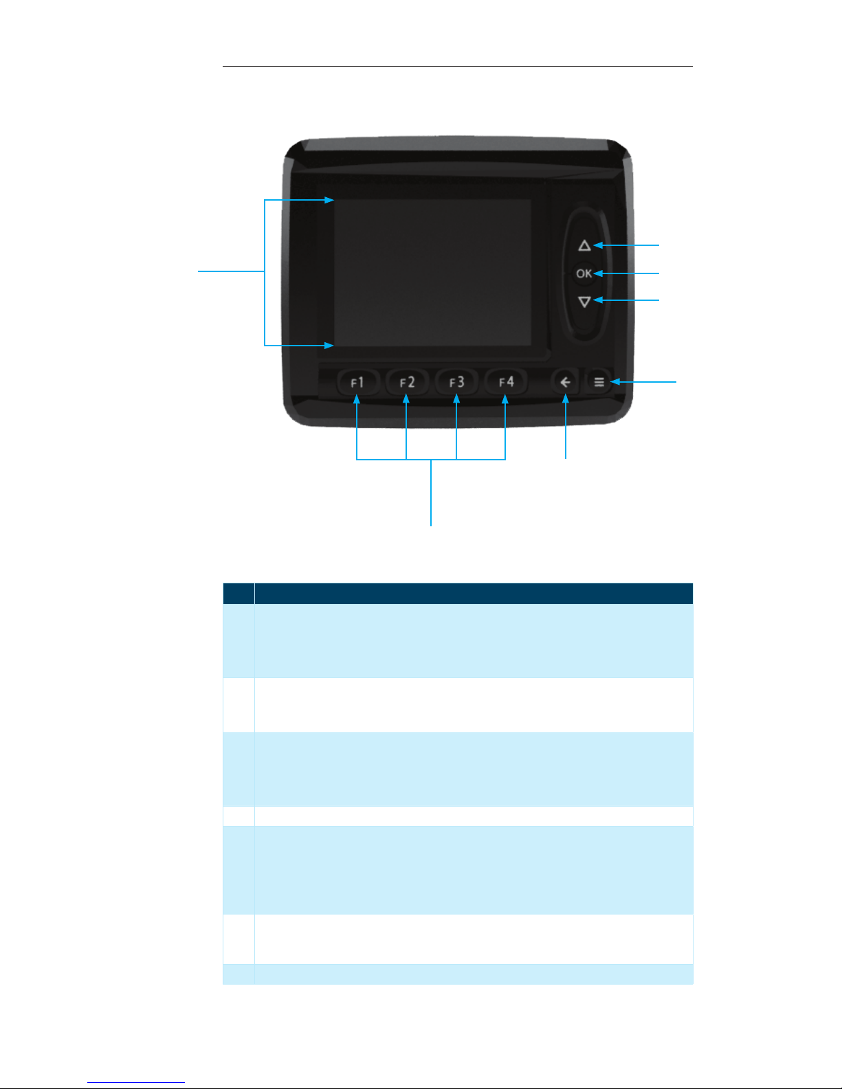
Each “Display Page” will have the
option to change the “Control
Device” for the Machine. To
change between different options
perform the following steps:
Press the “F4” button, this will
open the “Control Select” page.
Press the “F1” button to change
the control device
Use the “Up/Down” buttons to
select the desired control device
When the green light is on next to
the desired control device press
the “OK” button
Press the “F4” button to return to
the previous page
Table des matières


