Midea WDC-86E/KD Mode d'emploi

INSTALLATION & OWNER’S
MANUAL
WDC-86E/KD Wired Controller
Thank you for purchasing the wired controller.
This manual describes the safety precaution requirement of using this controller.


● Read this manual carefully and be sure you understand
the information before attempting to use the controller.
● Keep this manual where it is readily accessible after
reading it through.
● If another user operates the controller in the future, be
sure to hand over this manual to the new user.

Contents
Installation .........................................................................................................1
1. Safety Precautions .......................................................................................... 1
2. Accessories ..................................................................................................... 3
3. Installation Procedure...................................................................................... 4
Operation ........................................................................................................... 9
1. Safety Precautions .......................................................................................... 9
2. Parts of the Wired Controller......................................................................... 11
3. Icons in the Display ....................................................................................... 13
4. Operation Guide ............................................................................................ 13
Field Setting..................................................................................................... 24
1. Restore Factory Default ................................................................................ 24
2. Query and Set the Indoor Unit Address......................................................... 25
3. Commissioning Parameter Settings .............................................................. 26
4. Query Operations .......................................................................................... 34
5. Error Display.................................................................................................. 38
Troubleshooting .............................................................................................. 41

Installation
1. Safety Precautions
Please read these Safety Precautions carefully before installing the wired controller.
This manual classifies the precautions into WARNING and CAUTION. They both contain
important information regarding safety. Be sure to follow all the precautions below.
After completing the installation, conduct a trial operation to check for faults and explain to
the customer how to operate the controller with the aid of the operation manual. Ask the
customer to store the installation manual along with the operation manual for future
reference.
Ask your dealer or qualified personnel to carry out installation work.
Do not attempt to install the wired controller yourself. Improper installation may result in
leakage, electric shocks or fire.
Consult your local dealer regarding relocation and reinstallation of the wired controller.
Improper installation work may result in leakage, electric shocks or fire hazards.
Install the wired controller in accordance with the instructions in this manual.
Improper installation may result in water leakage, electric shocks or fire.
Failure to follow these instructions properly may result in personal
injury or loss of life.
Failure to observe these instructions properly may result in property
damage or personal injury, which may be serious depending on the
circumstances.
Identifier Meaning
Warning
Caution
Warning
●
●
●
1
Important Indicates a useful hint or additional information.

Be sure to use only the specified accessories and parts for installation work.
Failure to use the specified parts may result in the unit falling down, water leakage, electric
shocks or fire.
Install the wired controller on a foundation strong enough to withstand the weight of the
wired controller.
Insufficient strength may result in the wired controller falling down and causing injury.
Electrical work must be performed in accordance with the relevant local and national
regulations and with the instructions in this manual.
Be sure to use a dedicated power supply circuit only. Insufficient power circuit capacity and
improper workmanship may result in electric shocks or fire.
Always perform installation work with the power turned off.
pressing electric parts may result in electric shock.
Do not disassemble, reconstruct or repair.
This may result in electric shock and/or fire.
Make sure that all wiring is secured, the specified wires are used and that there is no strain
on the terminal connections or wires.
Improper connections or securing of wires may result in abnormal heat build-up or fire.
The choice of materials and installations must comply with the available national and
international standards.
●
●
To avoid leakage and electric shock due to entry of water or insects, fill the wiring through
hole with putty.
To avoid electric shocks, do not operate with wet hands.
Do not wash the wired controller with water, as this may result in electric shocks or fire.
When the follow me function of the wired controller is used, select the installation location
while considering it should be a place:
●
1).Where the average temperature in the room can be detected.
2).Which is not exposed to direct sunlight.
3).Which is not near a heat source.
4).Which is not affected by the outside air or air draught due to, for example,
opening/closing of doors, the air outlet of the indoor unit or the like.
●
●
●
●
Caution
2
●
●
●
●

2. Accessories
Please check that you have all the following parts.
Please prepare the following parts on site.
12
2
No. Name Schematic Qty. Remarks
No. Name Qty. Remarks
Philips head screw,
M4X25mm
2
3
1
2
3
4
5
Plastic support bar
φ5X16mm
Operation and Installation
Manual
86 electrical box
2-core shielded copper wires
Wiring tubes (insulation suite)
Big Phillips screwdriver
Small slotted screwdriver
General specification for electrical box,
which is embedded into the wall.
2*AWG16-AWG20, pre-embedded
into wall.
Longest wiring length is 200 metres.
Pre-embedded into wall.
To install the Philips screws.
To dismantle the bottom lid of the wired
controller.
Used to install the wired
controller on the electrical
box
Used to install the wired
controller on the electrical
box
1
1
1
1
1
1
3
/
Table 2.2
Table 2.1
Make sure to refer to "1. Safety Precautions" to determine the location.
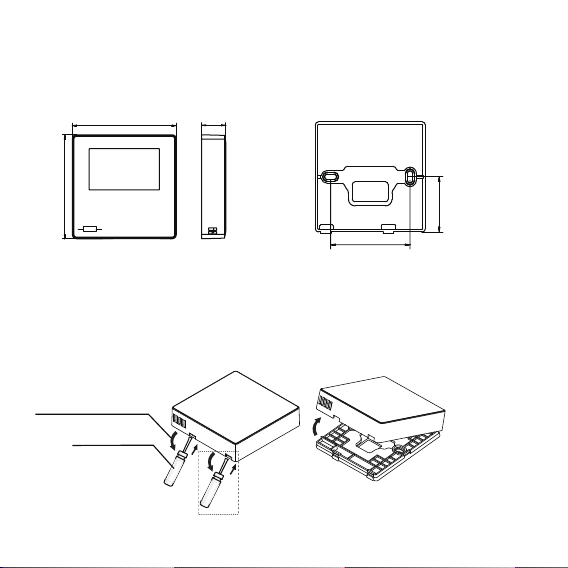
3-2 Structural Dimensions
3-3-1 Insert a small slotted-head screwdriver into the bottom slot of the wired controller and
rotate in the direction indicated to remove the rear cover of the wired controller. Pay attention
to the direction of rotation to prevent any damage to the rear cover of the wired controller. (see
Figure 3.3)
3-3 Rear Cover Installation
3. Installation Procedure
3-1 Determine Where to Install the Wired Controller
Figure 3.1 Figure 3.2
Screwdriver rotation direction
Slotted screwdriver
Figure 3.3
RT1
FOLLOW ME
4
86mm 20mm
86mm
60mm
41.7mm

3-3-2 Use a cutting tool to adjust the height of the two plastic support bars (accessory 2) to
match the standard length of the screw pillars of the electrical box to the wall surface. Make
sure that the support bars are level on the wall when the screw pillars of the electrical box are
mounted. (see Figure 3.4)
3-3-3 Once the heights of the plastic support bars are adjusted, fix the bars on the rear cover.
(see Figure 3.5)
Screw post of electrical box
Fix the support bars in the
direction of the arrow
Use a cutting tool to adjust the lengths of
the two plastic support bars
Figure 3.4
Figure 3.5
Warning
•When using the small slotted screwdriver to open the rear cover of the wired
controller, be careful not to damage the PCB inside.
• Do not touch the PCB of the wired controller.
5
h
h

Figure 3.6
To X1/X2 of indoor unit
Cross recessed
head screw Electrical box
Rear cover of
wired controller
3-3-4 Take the shielded wiring that has been pre-embedded in the wall, and thread it through
the wire hole of the rear cover. Use the Philips head screws (accessory 1) to fix the rear cover
of the wired controller to the electrical box via the support bars. Make sure that the rear cover
is not deformed after being installed (see Figure 3.6).
3-4-1 Wiring specification
• The rear cover may be deformed if the screw is too tight.
• Prepare the electrical box and the 2-core shielded copper wire on site.
• Do not touch the PCB of the wired controller.
Important
Caution
△
!
3-4 Wiring
6
Type 2-core shielded copper wire
AWG 16-20
Maximum 200m
Diameter
Length
Table 3.1
Table des matières
Autres manuels Midea Thermostat


Manuels Thermostat populaires d'autres marques

EWELLY
EWELLY EW-181 Manuel utilisateur

Prolon
Prolon T1100 Instructions d'installation

Computherm
Computherm Q20 Manuel utilisateur

Heatmiser
Heatmiser neoStat Manuel utilisateur

Aube Technologies
Aube Technologies TH111GFCI-NP 240 VCA Manuel utilisateur

Mars
Mars HEAT CONTROLLER IR Wireless Thermostat Manuel utilisateur


