MEYLE PLTA Instructions de fonctionnement
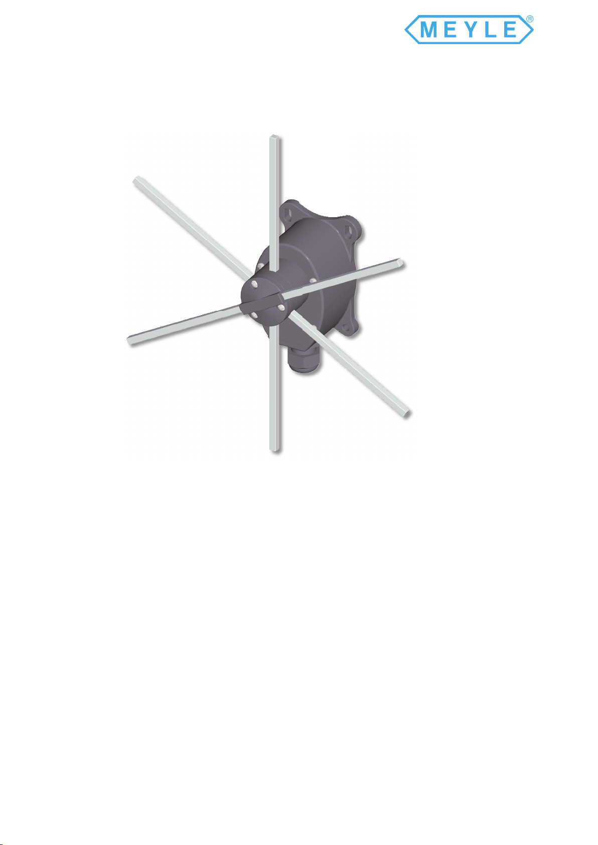
Position Limit Switches PLTA
PLTA is a position limit switch designed to control overhead travelling cranes, hoists and machine
tools. It operates as auxiliary controller of electrical motors through power interfaces, such as contactors or
PLCs.
PLTA is the latest generation of position limit switches: the peculiar design and the use of high
performing polymers ensure high resistance and endurance under the heaviest utilisation conditions.
Its design and overall dimensions facilitate installation and maintenance operations.
Both the enclosure and the head of PLTA are made of thermoplastic material (nylon reinforced
with breglass) ensuring wear resistance and protecting the equipment against water and dust. X-type rods
can move to 4 maintained positions.
Inner components are made of tecno-polymers guaranteeing a long life-cycle and constant performance even
at extreme temperatures.
PLTA is equipped with 1NC slow action switches or, upon request, 1NO switches.
All switches are of the positive opening type, thus suitable for safety functions.
Meyer Industrie-Electronic GmbH – MEYLE
Internet: www.meyle.de
E-Mail: [email protected]
Tel.: +49 54 81-93 85-0
Fax: +49 54 81-93 85-12
Carl-Bosch-Straße 8
49525 Lengerich/Germany
PLTA

The data and the products illustrated in this brochure may be modi ed without
notice. Under no circumstances can their description have a contractual value.
Tango Position Limit Switch
Technical Specifications
Conformity to Community Directives 73/23/CEE 93/68/CEE
Conformity to Standards EN 60204-1 EN 60947-1 EN60947-5-1
EN 60529 IEC 536
Ambient temperature Storage -40°C/+70°C
Operational -25°C/+70°C
Protection degree IP 65
Insulation category Class II
Cable entry Cable clamp M20
Operation frequency 3600 operations/hour max.
Technical Specifications of the Switches
Utilisation category AC 15
Rated operational current 3 A
Rated operational voltage 250 V
Rated thermal current 10 A
Rated insulation voltage 500 V~
Mechanical life 1x10⁶ operations
Terminal referencing According to EN 50013
Connections Screw-type terminals
Page 2
Standard Limit Switch Codes
Limit switches are equipped with 1NC switches MY1001PI.
Code No. of switches Rod
length Actuating travel
MY20001 2 300 mm
MY20005 2 250 mm
MY20006 2 200 mm
MY30001 3 300 mm
MY30002 3 250 mm
MY30003 3 200 mm
MY40001 4 300 mm
MY40006 4 250 mm
MY40007 4 200 mm
Meyer Industrie-Electronic GmbH – MEYLE
Internet: www.meyle.de
E-Mail: [email protected]
Tel.: +49 54 81-93 85-0
Fax: +49 54 81-93 85-12
Carl-Bosch-Straße 8
49525 Lengerich/Germany

TER Tecno Elettrica Ravasi s.r.l. - Via San Vigilio 2 - 23887 Olgiate Molgora (LC) - Italy
Tel. +39 039 9911011 - Fax +39 039 9910445
Tango Position Limit Switch
The data and the products illustrated in this brochure may be modi ed without
notice. Under no circumstances can their description have a contractual value.
Overall Dimensions
Maximum Actuating Dimensions
Rods with 4 maintained positions
Pre-travel angle for
rotation contact operation 34°
Maximum rotation angle for
each maintained position 60°
Average angle for the
mechanical tripping 30°
Maintained positions each 60°
In order to ensure proper operations, the dimensions
shall not be increased; anyhow, they can be decreased,
taking into account that the closer the impact point is
to the center of the head, the higher the impact and
the mechanical wear of rod and shaft are.
Rod Length
300mm
200mm
250mm
150mm rod
125mm rod
100mm rod
Actuating point 60mm
Actuating point 93mm
Actuating point 76mm
Meyer Industrie-Electronic GmbH – MEYLE
Internet: www.meyle.de
E-Mail: [email protected]
Tel.: +49 54 81-93 85-0
Fax: +49 54 81-93 85-12
Carl-Bosch-Straße 8
49525 Lengerich/Germany

The data and the products illustrated in this brochure may be modi ed without
notice. Under no circumstances can their description have a contractual value.
Tango Position Limit Switch
Page 4
Detailed Drawing
Meyer Industrie-Electronic GmbH – MEYLE
Internet: www.meyle.de
E-Mail: [email protected]
Tel.: +49 54 81-93 85-0
Fax: +49 54 81-93 85-12
Carl-Bosch-Straße 8
49525 Lengerich/Germany

TER Tecno Elettrica Ravasi s.r.l. - Via San Vigilio 2 - 23887 Olgiate Molgora (LC) - Italy
Tel. +39 039 9911011 - Fax +39 039 9910445
Tango Position Limit Switch
The data and the products illustrated in this brochure may be modi ed without
notice. Under no circumstances can their description have a contractual value.
Components
Reference Description
01 Upper rod support
02 Rod 6x6x200 mm
Rod 6x6x250 mm
Rod 6x6x300 mm
03 Screw 3.9x16
04 Toothed washer
05 Lower rod support
06 O-ring 2056
07 Cam 60° sx
Cam 60° dx
Cam 110° sx
Cam 110° dx
Cam for right-left slowing
08 Screw 3.5x12
09 Switch holder plate
10 Elastic ring
11 Pin for notch
12 Spring
13 Enclosure
14 Cable clamp M20
15 Cable clamp gasket
16 Cable clamp nut
17 Wheel for notches
18 Shaft
19 1NO switch
1NC switch
20 Drive bush
21 Cover with gasket
22 Ring for rod support
23 Middle rod support
24 Screw 4x20
Meyer Industrie-Electronic GmbH – MEYLE
Internet: www.meyle.de
E-Mail: [email protected]
Tel.: +49 54 81-93 85-0
Fax: +49 54 81-93 85-12
Carl-Bosch-Straße 8
49525 Lengerich/Germany

The data and the products illustrated in this brochure may be modi ed without
notice. Under no circumstances can their description have a contractual value.
Page 5
The PLTA limit switch is an electromechanical device for low voltage control circuits (EN 60947-1, EN 60947-5-1) for use as
electric equipment on machines (EN 60204-1) in compliance with the essential requisites of the Low Voltage Directive 73/23/
EEC and the Machine Directive 89/392/EEC.
The limit switch is designed for use in industrial environments with even very severe climatic conditions (working temperatures
from -25°C to +70°C and is suitable for use in tropical environments). The equipment is not suitable for use in environments
with a potentially explosive atmosphere, in the presence of corrosive agents or high percentage of sodium chloride (saline mist).
Contact with oil, acids and solvents may damage the equipment. The limit switches is not suitable for use in environments
with a potentially explosive atmosphere.
The PLTA limit switch must be fastened through the holes on the side of the case (13); in particular the top holes are slots to
facilitate fastening and adjustment of the limit switch, which must be suitably position to ensure correct impact on the drive rods
(02). To prevent malfunctions or problems; examine the technical documentation to view the recommended impact points.
Turn the closing screws (24) and loosen the closure of the rod holder (01, 05, 23), then you can move the rods to adjust
them; afterwards, tighten the closing screws (24) with a force of 100cN m to ensure secure fastening of the rod holder. We
recommend adjusting the impact point of the rods (02) by adjusting the fastening of the entire limit switch and not simply
moving the rods.
The switches (19) of the PLTA are designed for the auxiliary control of contacts or electromagnetic charges in general (utilization
category AC-15 in accordance with EN 60947-5-1). The switches (19) have contacts with positive mechanical opening operation
(EN 60947-5-1). Do not connect more than one phase for the switches (19). Never oil or grease the switches (19).
To facilitate wiring the switches (19) the limit switches can be removed from the case (13); after wiring, the switches (19)
must be replaced correctly in the case (13), then assemble the cover (21) and tighten the screws (03) with a minimum force
of 100cN m.
Installation of the limit switches should be done by competent, trained personnel. The electric wiring must be done in a
workmanlike manner by quali ed personnel in compliance with the regulations in force.
Before performing installation and maintenance of the limit switches, disconnect the machine from the power mains.
Operations for installation and correct wiring of limit switch
- fasten the limit switch securely to prevent malfunctions during use of the device; to fasten it, use the holes on the
sides of the case (13); fasten the limit switch so that the drive rods (02) function correctly, by examining the technical
documentation to identify the recommended point of impact; adjust the (02), by turning the closing screws (24) on the
relative rod holder elements (01, 05, 23). Afterwards, tighten the screws (24) with a force of 100cN m
- introduce the multi-pole wire in the limit switch through the wire clamp (14)
strip the multi-pole cable for a length suf cient to wire it to the switches (19)
- wire the switches (19) as shown in the wiring diagrams on each (19); tighten the wires into the terminals of the switches
with a torque of 0.8 Nm (insertability of wires into the switch terminals equal to 2x1.5mm2 – 1x2.5 mm2)
- after wiring tighten the wire in the wire clamp (14)
- close the limit switch with its cover (21) with the closing screws (03); applying a force of at least 100cN m
Operations of routine maintenance
- check the correct tightening of the closing screws (03) on the cover (21)
- check the conditions of the wires on the switches (19) (if necessary, tighten the screws on the terminals)
- tighten the multi-pole wire in the wire clamp (14)
- check the conditions of the complete limit switch (01, 02, 05, 13, 21, 23)
- check the fastening of the limit switch
Any change to parts of the limit switch will invalidate the rating plate data and identi cation of the device, and render the
warranty null and void. In case of replacement of any part, use only original replacements.
MEYLE is not liable for damages caused by improper use of the device and installation which is not made correctly.
Use and Maintenance Instructions
Meyer Industrie-Electronic GmbH – MEYLE
Internet: www.meyle.de
E-Mail: [email protected]
Tel.: +49 54 81-93 85-0
Fax: +49 54 81-93 85-12
Carl-Bosch-Straße 8
49525 Lengerich/Germany
Table des matières


