Metropolitan Industries ion Technologies Ion+ Connect Manuel utilisateur

www.ionproducts.net
The Ion+ Connect is a residential
sump/sewage ejector pump controller
equipped with the Ion®level sensor
and integrated cellular module for
communicating with the Ion+ Connect
app. The device will run one or
two manual pumps up to 12 FLA,
can sense up to 72” of water, has
customizable start/stop/alarm levels,
and provides alarm notications via
SMS text for alarms like high water,
pump fail, power fail, and many more.
PUMP
TEST
REMOTE
ALARM
INPUT
DIGITAL
LEVEL
SENSOR
REMOTE
ALARM
CONTACT
INPUT:
120VAC 60Hz 15A
OUTPUT:
120VAC 60Hz 12FLA 72LRA
LOCK/
UNLOCK
SILENCE/
RESET
What'sin the Box
The Ion+ Connect comes with:
1. Ion+ Connect
Pump Controller equipped with 10’ 115
VAC cord.
2. Rechargeable Lithium Ion Battery
Powers the Ion+ Connect in the event of
power loss.
3. Ion Sensor with pipe clamp
Connects to Ion+ Connect to provide
level signal.
4. Antenna
1
2
3
4
Ion+®Connect
Operation ManualIon+®Connect
Digital Level Control Switch and Alarm
with Internal Cellular Module
Ion+®Connect
Digital Level Control Switch and Alarm
with Internal Cellular Module
www.ionproducts.net
Page 2 of 24
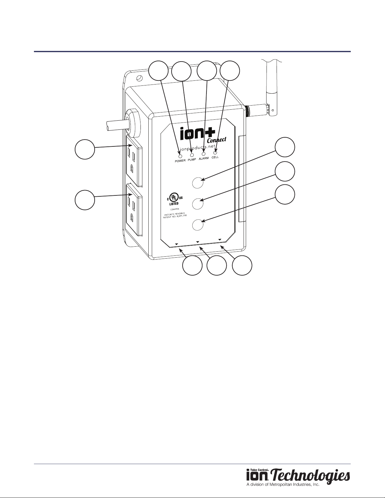
Features
1. Power LED
Indicates the power status of unit. Refer to the
LED section for details.
2. Pump LED
Indicates the pump status. Refer to the LED
section for details.
3. Alarm LED
Indicates alarm status. Refer to the LED section
for details.
4. Cellular LED
Indicates cellular connectivity status. Refer to the
LED section for details.
5. Pump Test
Hold down the button until the device beeps to
manually run pump(s).
6. Silence / Reset
Momentarily push for Alarm Silence. Hold to
reset unit.
7. Lock / Unlock
Press and hold until the unit beeps twice to unlock
it.
8. Remote Alarm Input
Aux alarm input connection via 6P2C (RJ11) jack
(must be powered).
9. Digital Water Level Sensor
Connection for Ion Sensor.
10. Remote Alarm Contact (Output)
Normally closed, dry contacts via 6P2C (RJ11)
jack.
11. Pump 1/ Default Outlet
12. Pump 2/ Secondary Outlet
PUMP
TEST
REMOTE
ALARM
INPUT
DIGITAL
LEVEL
SENSOR
REMOTE
ALARM
CONTACT
INPUT:
120VAC 60Hz 15A
OUTPUT:
120VAC 60Hz 12FLA 72LRA
LOCK/
UNLOCK
SILENCE/
RESET
123 4
5
6
7
8 9 10
12
11

Ion+®Connect
Digital Level Control Switch and Alarm
with Internal Cellular Module
www.ionproducts.net
Page 3 of 24
TesTing Your ion+ ConneCT
WARNING: Do not plug in the device until instructed.
WARNING: Do not install the lithium ion battery in the device until instructed.
CAUTION: The device must be allowed to reach room temperature or you run the risk of the device alarming
once it’s plugged in. Your Ion+ Connect is equipped with a temperature sensor. If the device is too hot or too
cold based on the factory settings (over 110° F or under 45° F) the temperature sensor will alarm. If your Ion+
Connect alarms when it is plugged in, please see Troubleshooting, Page 18.
NOTE: IF YOU ARE INSTALLING THE ION+ CONNECT TO AN EXISTING SUMPRO MODEL 75, PLEASE
CONTACT MANUFACTURER FIRST.
1. Install Ion+ Connect and Ion Sensor
a. Mount the Ion+ Connect unit to wall with appropriate screws (not included). (See Figure A)
b. Determine the preferred pipe bracket mounting orientation for the Ion sensor (See Figure B).
c. Mount the bracket to the Ion sensor with the screw already provided in the Ion sensor
(See Figure C)
d. Mount the hose clamp with attached sensor around the discharge pipe at the predetermined level. The
sensor cable should remain outside of the hose clamp (See Figure D). Tighten the hose clamp.
FIGURE B
or
Optional
bracket
5-5/8”
2-3/16”
(4) 3/16” Dia.
Mounting Holes
FIGURE A

Ion+®Connect
Digital Level Control Switch and Alarm
with Internal Cellular Module
www.ionproducts.net
Page 4 of 24
FIGURE C FIGURE D
FIGURE E
e. Pull the pump power cord and the Ion sensor cord through sump pit lid.
f. If you have a simplex pump system (this is only one pump), plug your pump into the top outlet on the left side
of the Ion+ Connect. If you have a duplex system, plug the second pump into the bottom outlet on the Ion+
Connect.
g. Plug the Ion sensor into the jack on the bottom labeled "Digital Level Sensor".
Note: The included Ion digital water level sensor has a 72” range. The range of the sensor is the maximum
distance between the pump on and off levels. The off level is approximately at the bracket mounting screw of the
sensor.
CAUTION: The bottom of sensor should not be mounted lower than the suction inlet of the pump. When
installing the Ion sensor with the pipe mounting bracket, be sure not to set the sensor too low (below the
inlet of the pump) or too high (allowing water to re-enter the inlet drain tile pipe) on the pump discharge pipe. The
Ion sensor must be installed above the inlet of the pump to prevent airlocking as shown in the installation diagram

Ion+®Connect
Digital Level Control Switch and Alarm
with Internal Cellular Module
www.ionproducts.net
Page 5 of 24
(See Figure E).
To prevent ooding do not set the on point of the pump higher than the top of the basin. This setting is congured
in the Ion+ Connect app.
NOTE: If you purchased a pump with the Ion sensor already mounted to the pump (See Figure F) and the installation
requires the sensor be mounted to the pipe. You can purchase the pipe-mount bracket separately, PN: IN-SPB1-1.
FIGURE F
4" Range
On
High Water
Alarm
Factory default settings
User adjustable up to 72”
NOTE: The high water alarm level should be set at 2" above the lead pump start setting.
WARNING: As a reminder, do not install the lithium ion battery in the device until instructed.
2. Install Lithium Ion Battery
The Ion+ Connect comes with a rechargeable lithium ion battery to provide backup power in times of power loss. In
order to continue to send out alarm notications and sound the alarms in times of power loss, this must be installed.
Note: This battery will not run your pump.
a. The battery should be installed while the LEDs on the front of the Ion+ Connect are still ashing (about 5
seconds).
b. Remove the slide cover on right edge of unit.
c. Install battery (See Figure G), observing proper orientation/polarity (positive battery terminal/button toward
top).
d. Reinstall the battery cover.
3. Power On
Plug the Ion+ Connect's AC power cord into a dedicated outlet. Alternatively, if you have a UPS/battery backup
system plug the Ion+ Connect into it instead.
2"

Ion+®Connect
Digital Level Control Switch and Alarm
with Internal Cellular Module
www.ionproducts.net
Page 6 of 24
FIGURE G
ACTivATing Your ion+ ConneCT
Adding a Device to Your Account
1. Download the Ion+ Connect app from the Apple app store or the Google Play store. Alternately, visit app.ion.
cloud for the web-based app if not using an Apple or Android device
.
2. Once you have created an account and logged in, tap the Add Device button.

Ion+®Connect
Digital Level Control Switch and Alarm
with Internal Cellular Module
www.ionproducts.net
Page 7 of 24
3. Next, tap the Scan QR Code button, and scan the QR code on the top of your Ion+ Connect (See Figure H).
Note: If using the web-based app, you will need to manually enter the digits to the left of the QR code.
1A23B4
5C67D
89123
45678
91EF2
FIGURE H
Note: Figure H is a sample image, don't scan the QR code in this gure.
4. Tap the checkbox to conrm your device is plugged in and tap done.

Ion+®Connect
Digital Level Control Switch and Alarm
with Internal Cellular Module
www.ionproducts.net
Page 8 of 24
Activating the Ion+ Connect
1. Here you will see the cellular plan selection screen. Select your desired plan, conrm your renewal options,
and enter your payment details.

Ion+®Connect
Digital Level Control Switch and Alarm
with Internal Cellular Module
www.ionproducts.net
Page 9 of 24
2. Once payment is veried, the app will start the process of activating your device. This may take several
minutes; once complete, your device is activated and setup can commence.
Completing Device Setup
1. The Ion+ Connect will now connect to the cloud, a process which may take several minutes. You will notice
the cell LED change from solid amber to solid green once this process is complete. Tap next. Note: If the
connection stalls for more than 3 minutes, hold the reset button until the device beeps twice and restart the
activation process.

Ion+®Connect
Digital Level Control Switch and Alarm
with Internal Cellular Module
www.ionproducts.net
Page 10 of 24
2. Allow the device to synchronize data, and tap next.
3. Choose basic or advanced setup and proceed through the setup options. These settings can be changed at
any time once setup is completed.
4. On the recipient list screen, you will already be added as a recipient based on the information you entered
when you created your account. You can add additional recipients now or at a later time.
Table des matières


