9
OPERATION MANUAL
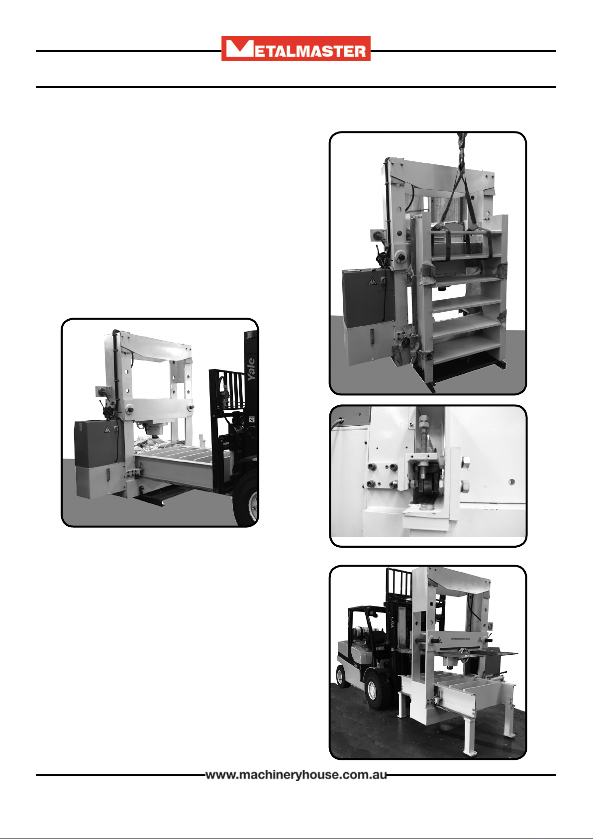
3 INSTALLATION
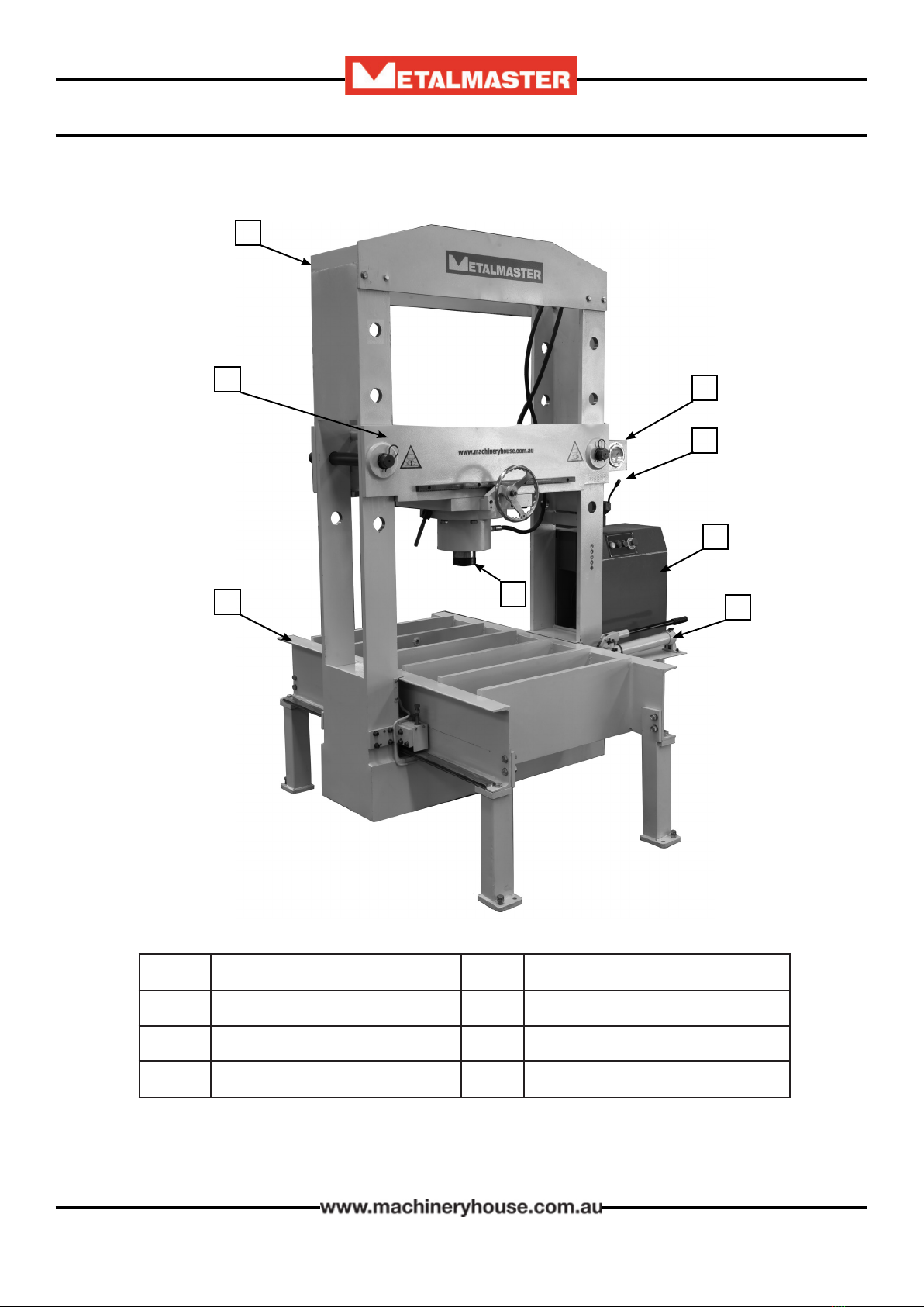
Position the press assembly in a suitable location. e dimensions can be found in the specications
list on page 4. e base of the press should sit on a concrete oor at least 150mm thick.
NOTE ! e press must be permanently mounted to the oor with bolts through the four legs.
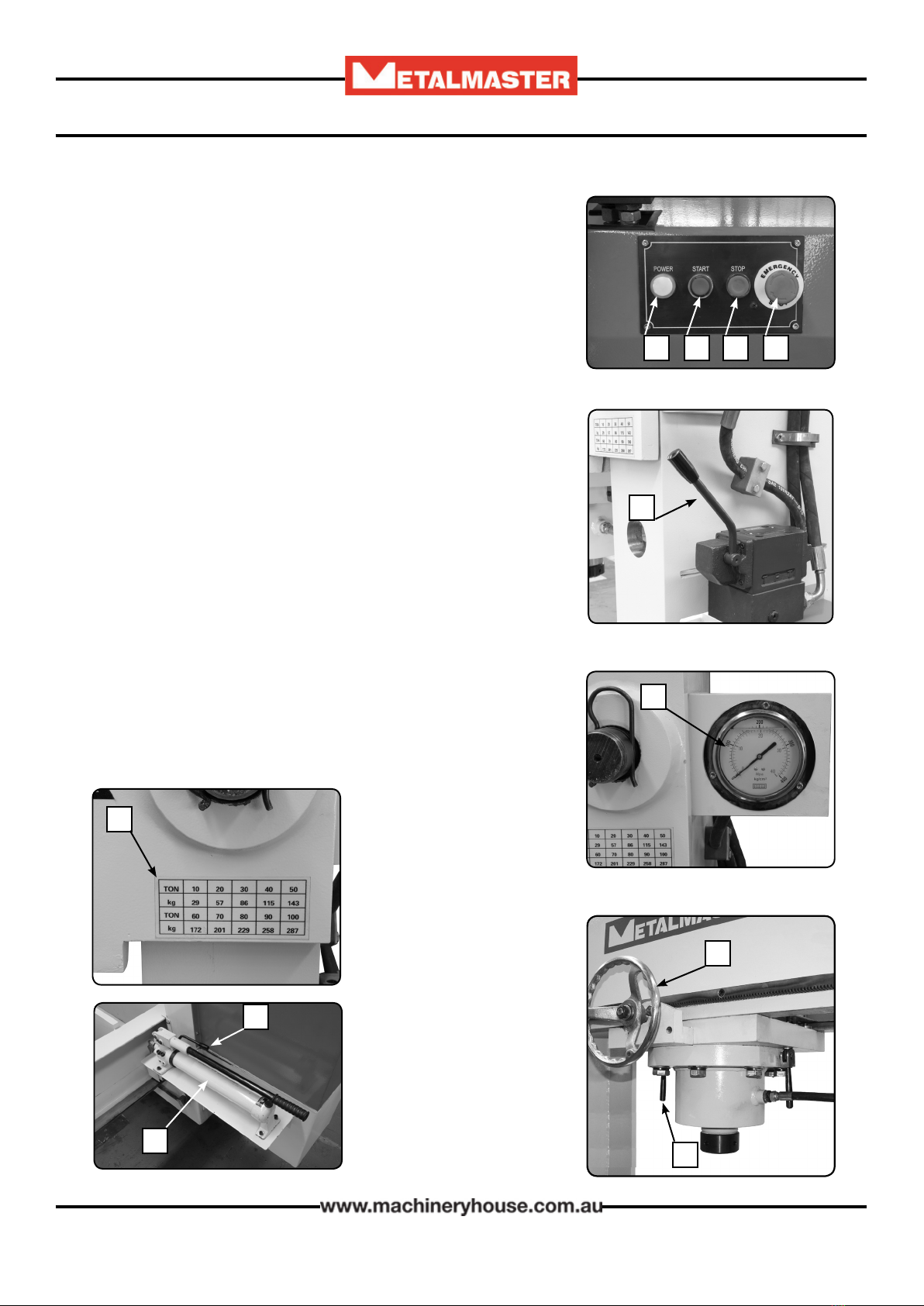
Fig. 5
e press should be level and stable. Place a level across the and
along the table and adjust until the table is level.
e table legs are tted with and adjusting screw and a hole for
the hold down bolt
WARNING
e machine is top heavy when the bolster
is in the top position
3.3 HYDRAULIC OIL TANK
Once the press has been installed and bolted to the oor the
hydraulic oil level needs to checked in the 40 ltr tank before
operating. e oil level should be half way up the site glass
on the side of the tank (Fig. 6) Check all hydraulic hoses
to be sure the ttings and couplers are tight and leak free.
Check the hose positions to be sure the hoses are located in
an area where they will avoid damage during press opera-
tions.
3.2 ELECTRICAL CONNECTION
e press needs to be connected to the power supplied. e power requirements are listed below
VOLTAGE.........................................415 Volts 3 Phase 50 Hz
AMPS.................................................15 Amps
e press is supplied without any lead and requires a qualied electrician to connect the machine
to the power supply. If a plug and lead is to be tted then either a service engineer of qualied elec-
trician ahould be used.
WARNING
is machine has an electrical hazard.
Electrical cabinets must not be opened except by a
qualied electrician.
Fig. 6
3.1 PLACEMENT & LEVELING