Mercury 4000 MPC GEN II Manuel utilisateur

90-8M0103111 FEBRUARY 2015 © 2015 Mercury Marine Page 1 / 22
4000 MPC GEN II PISTOL GRIP REMOTE
CONTROL INSTALLATION INSTRUCTIONS
IMPORTANT: This document guides our dealers, boatbuilders, and company service personnel in the proper installation or
service of our products. If you have not been trained in the recommended servicing or installation procedures for these or
similar Mercury Marine products, have the work performed by an authorized Mercury Marine dealer technician. Improper
installation or servicing of the Mercury product could result in damage to the product or personal injury to those installing or
operating the product.
NOTE:
After completing installation, place these instructions with the product for the owner's future use.
Pistol Grip Remote Control with Fingertip Neutral Lock Release
24953
Notice to Installer
Throughout this publication, Warnings and Cautions (accompanied by the International Hazard Symbol) are used to alert the
installer to special instructions concerning a particular service or operation that may be hazardous if performed incorrectly or
carelessly. Observe them carefully.
These "Safety Alerts," alone, cannot eliminate the hazards that they signal. Strict compliance to these special instructions
when performing the service, plus common sense operation, are major accident prevention measures.
! WARNING
Indicates a hazardous situation which, if not avoided, could result in death or serious injury.
! CAUTION
Indicates a hazardous situation which, if not avoided, could result in minor or moderate injury.
NOTICE
Indicates a situation which, if not avoided, could result in engine or major component failure.
IMPORTANT: Indicates information or instructions that are necessary for a particular step or action.
NOTE: Indicates information that helps in the understanding of a particular step or action.
This instruction sheet has been written and published by the service department of Mercury Marine to aid installers when
installing the products described herein.

4000 MPC GEN II PISTOL GRIP REMOTE CONTROL INSTALLATION INSTRUCTIONS
Page 2 / 22 90-8M0103111 FEBRUARY 2015
It is assumed that these personnel are familiar with the installation procedures of these products, or like or similar products
manufactured and marketed by Mercury Marine. Also, that they have been trained in the recommended installation
procedures of these products, which includes the use of mechanics’ common hand tools and the special Mercury Marine or
recommended tools from other suppliers.
We could not possibly know of and advise the marine trade of all conceivable procedures by which an installation might be
performed and of the possible hazards or results of each method. We have not undertaken any such wide evaluation.
Therefore, anyone who uses an installation procedure or tool that is not recommended by the manufacturer must first
completely satisfy himself that neither his nor the product’s safety will be endangered by the installation procedure selected.
All information, illustrations, and specifications contained in this manual are based on the latest product information available
at time of publication. As required, revisions to this manual will be sent to all OEM boat companies.
GEN II Pistol Grip with Fingertip Neutral Lock Release Panel Mount Remote
Control Features and Operation
1 - Neutral lock button
2 - Throttle only button
3 - Power trim switch
4 - Lanyard stop switch
5 - Control handle
6 - Control handle friction adjustment nut
1. Neutral lock button ‑ Prevents unintentional shifting into gear. To shift into gear, press and hold the neutral lock button
and move the control handle out of neutral.
2. Throttle only button ‑ The throttle only button allows throttle advancement without shifting the engine. The throttle only
button disengages the shifting mechanism from the control handle. The throttle only button can be pressed and held in
only when the remote control handle is in the neutral position. While holding the throttle only button in, move the throttle
handle forward to assist in starting the engine.
3. Power trim (and trailer MCM only) switch (if equipped) ‑ Used to trim or raise drive unit for trailering, launching,
beaching, or shallow water operation.
4. Lanyard stop switch (if equipped) ‑ The purpose of a lanyard stop switch is to turn off the engine when the operator
moves far enough away from the operator's position (as in accidental ejection from the operator's position) to activate the
switch. Tiller handle outboards and some remote control units are equipped with a lanyard stop switch. A lanyard stop
switch can be installed as an accessory ‑ generally on the dashboard or side adjacent to the operator's position.
• The lanyard is a cord usually between 122 and 152 cm (4 and 5 feet) in length when stretched out, with an element
on one end made to be inserted into the switch and a snap on the other end for attaching to the operator. The
lanyard is coiled to make its at‑rest condition as short as possible to minimize the likelihood of lanyard entanglement
with nearby objects. Its stretched‑out length is made to minimize the likelihood of accidental activation should the
operator choose to move around in an area close to the normal operator's position. If it is desired to have a shorter
lanyard, wrap the lanyard around the operator's wrist or leg, or tie a knot in the lanyard.
57834
1
2
3
4
5
6

4000 MPC GEN II PISTOL GRIP REMOTE CONTROL INSTALLATION INSTRUCTIONS
90-8M0103111 FEBRUARY 2015 Page 3 / 22
•Important safety information: The purpose of a lanyard stop switch is to stop the engine when the operator
moves far enough away from the operator's position to activate the switch. This would occur if the operator
accidentally falls overboard or moves within the boat a sufficient distance from the operator's position. Falling
overboard and accidental ejections are more likely to occur in certain types of boats such as low‑sided inflatables,
bass boats, high performance boats, and light, sensitive handling fishing boats operated by a hand tiller. Falling
overboard and accidental ejections are also likely to occur as a result of poor operating practices such as sitting on
the back of the seat or gunwale at planing speeds, standing at planing speeds, sitting on elevated fishing boat
decks, operating at planing speeds in shallow or obstacle‑infested waters, releasing your grip on a steering wheel or
tiller handle that is pulling in one direction, drinking alcohol or consuming drugs, or daring high speed boat
maneuvers.
• While activation of the lanyard stop switch will stop the engine immediately, a boat will continue to coast for some
distance depending upon the velocity and degree of any turn at shut down. However, the boat will not complete a
full circle. While the boat is coasting, it can cause injury to anyone in the boat's path as seriously as the boat would
when under power.
• We strongly recommend that other occupants be instructed on proper starting and operating procedures should
they be required to operate the engine in an emergency (e.g. if the operator is accidentally ejected).
! WARNING
If the operator falls out of the boat, stop the engine immediately to reduce the possibility of serious injury or death from
being struck by the boat. Always properly connect the operator to the stop switch using a lanyard.
! WARNING
Avoid serious injury or death from deceleration forces resulting from accidental or unintended stop switch activation. The
boat operator should never leave the operator's station without first disconnecting the stop switch lanyard from the operator.
Accidental or unintended activation of the switch during normal operation is also a possibility. This could cause any,
or all, of the following potentially hazardous situations:
• Occupants could be thrown forward due to unexpected loss of forward motion ‑ a particular concern for passengers
in the front of the boat who could be ejected over the bow and possibly struck by the gearcase or propeller.
• Loss of power and directional control in heavy seas, strong current, or high winds.
• Loss of control when docking.
5. Control handle ‑ Operation of the shift and throttle is controlled by the movement of the control handle. Push the control
handle forward from neutral with a quick firm motion to the first detent for forward gear. Continue pushing forward to
increase speed. Pull the control handle back from neutral with a quick firm motion to the first detent for reverse gear.
Continue pushing back to increase speed.
NOTICE
Failure to rotate the propeller shaft when shifting gears or forcing the shift mechanism while the engine is not operating can
result in product damage. If you must shift gears with the engine off, manually rotate the propeller shaft in the appropriate
direction.
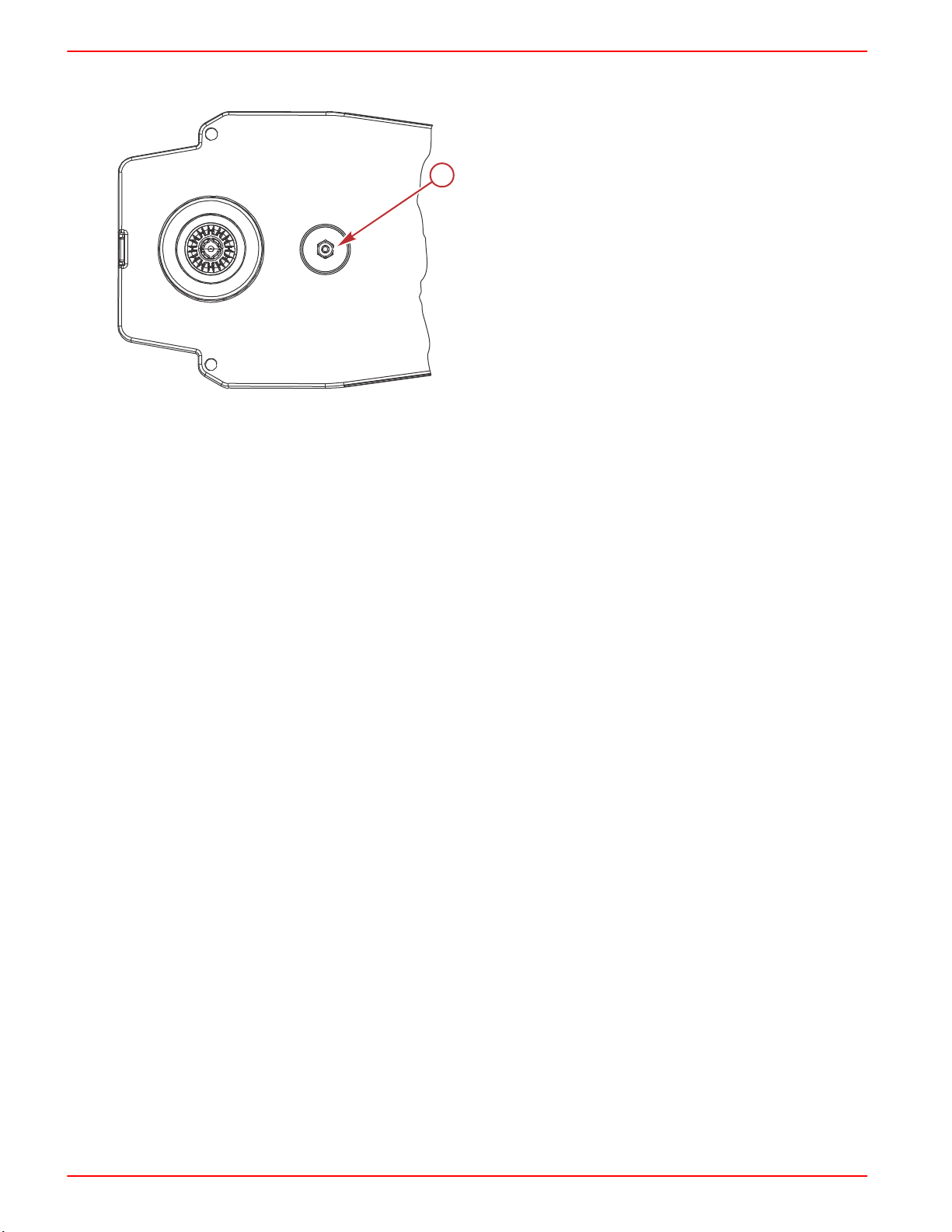
6. Control handle friction adjustment nut ‑ This nut can be adjusted to increase or decrease the tension on the control
handle. This will help prevent creep of the remote control handle. Turn the screw clockwise to increase the tension, and
counterclockwise to decrease the tension. The control handle friction adjustment nut is factory set to a predetermined
amount of friction but can be adjusted to a desired tension.
NOTE: Control handle friction adjustments must be made prior to the installation of the remote control module to the
bezel.
4000 MPC GEN II PISTOL GRIP REMOTE CONTROL INSTALLATION INSTRUCTIONS
Page 4 / 22 90-8M0103111 FEBRUARY 2015
IMPORTANT: Control handle friction is necessary for proper mechanical control operation. Insufficient friction may cause
undesirable throttle arm operation.
a - Control handle friction adjusting nut
GEN II Series Panel Mount Remote Control Installation
Required Mounting Clearances for GEN II Pistol Grip Fingertip Lock Release Panel
Mount Control
IMPORTANT: GEN II throttle and shift cables are required with the GEN II remote controls. The remote control cables must
be the correct length. Sharp bends when the cables are too short result in kinks. Cables that are too long require unnecessary
bends and/or loops. Both conditions place extra stress on the cables resulting in unfavorable shift and throttle operation. The
minimum bend radius of the remote control cable is 30.5 cm (12 in.). For applications that require a smaller than the minimum
radius, multiple bends or lengths longer than 5.5 m (18 ft), Mercury/Quicksilver GEN II Platinum or Premium cables are
required. Refer to the Mercury Precision Parts Accessories Guide.
57833
a

4000 MPC GEN II PISTOL GRIP REMOTE CONTROL INSTALLATION INSTRUCTIONS
90-8M0103111 FEBRUARY 2015 Page 5 / 22
IMPORTANT: Ensure the remote control has a minimum of 45.7 cm (18 in.) straight routing clearance for the control cables
and does not contact other components. Refer to the shaded area.
a - Maximum mounting panel thickness
b - Do not use anchors, clamps, cable ties, or secure any harnesses or other items within 45.7 cm (18 in.) of the control
cables exiting the remote control module
c - Hand clearance
GEN II Series Panel Mount Remote Control Bezel Installation
NOTE: This remote control should be installed on the starboard side only.
41.27 mm
(1.625 in.)
136.52 mm
(5.375 in.)
76.5 mm
(3.00 in.)
25.4 mm
(1.00 in.)
217.50 mm
(8.56 in.)
40.6 mm
(1.60 in.)
142.2 mm
(5.60 in.)
b
a
c
c
25027
(8.62 in.)
R 218.9 mm
(2.00 in.)
50.8 mm
(18.00 in.)
457. mm
(5.81 in.)
147.5 mm
(7.78 in.)
197.6 mm
120.6 mm
(4.75 in.)
353.1 mm
(13.9 in.)
303.3 mm
(11.94 in.)

4000 MPC GEN II PISTOL GRIP REMOTE CONTROL INSTALLATION INSTRUCTIONS
Page 6 / 22 90-8M0103111 FEBRUARY 2015
IMPORTANT: When selecting the mounting area for the panel mount remote control, the area located directly behind the
mounting panel must have sufficient clearance for the control module, wiring harness, control cables, and control cable
movement. Refer to the Required Mounting Clearances for GEN II Pistol Grip Fingertip Lock Release Panel Mount Control.
IMPORTANT: Allow sufficient clearance for the control handle movement. Avoid interference with the boat components or
other accessories. Ensure the control handle clears the dash, seats, steering wheel, and any other obstructions.
Bezel Location and Drilling Mounting Area
IMPORTANT: The mounting surface for the bezel should be a flat and ridged platform, preferably constructed with one of the
following: aluminum, fiberglass, or plywood reinforced with fiberglass. One layer of vinyl between the bezel and ridged
mounting platform is acceptable. All foam should be removed between the bezel and the ridged mounting platform. To ensure
a robust installation, the mounting platform must not exceed 2.54 cm (1 in.) thickness.
NOTE: The remote control template supplied with this instruction sheet will allow the installer to rotate and mount the remote
control module in 30° increments. Allow for proper clearance behind the mounting area when selecting the mounting area for
the remote control.
1. Locate the area of the boat where the panel mount remote control is to be mounted. Allow sufficient clearance for the
control handle movement, remote control module, and control cables behind the mounting area.
2. Use the template supplied with these instructions and place the template over the mounting platform surface.
3. Secure the template to the mounting platform surface with tape. Cut and drill the mounting platform surface as instructed
on the template.
IMPORTANT: After cutting and drilling the mounting platform, use a suitable tool to remove all of the sharp edges on the
inside and outside of the mounting platform cutout to prevent chafing of the harnesses.
a - Mounting surface
b - Maximum mounting platform
thickness 2.54 cm (1 in.)
c - Template
17436
a
b
c

4000 MPC GEN II PISTOL GRIP REMOTE CONTROL INSTALLATION INSTRUCTIONS
90-8M0103111 FEBRUARY 2015 Page 7 / 22
Bezel Installation
Install and secure the bezel to the mounting platform surface. Tighten the bezel mounting screws to the specified torque.
a - Screw (0.250‑20 x 1.750 in.) (3)
b - Washer (3)
c - Nut (0.250‑20) (3)
d - Mounting platform
Description Nm lb‑in. lb‑ft
Bezel mounting screw (3) Aluminum or fiberglass 5.6 50 –
Plywood 4 35.4 –
NOTE: On some boat installations, it may be helpful to first make the cutout for the remote control using the supplied
template, and route the control cables through the boat before installing the cables to control module.
Selecting and Routing Remote Control Cables
Mercury - Mariner - Force - Mercury MerCruiser
Refer to the Mercury Precision Parts Accessories Guide for the available shift and throttle cables for your application.
IMPORTANT: GEN II throttle and shift cables are required with the GEN II remote controls. The remote control cables must
be the correct length. Sharp bends when the cables are too short result in kinks. Cables that are too long require unnecessary
bends or loops. Both conditions place extra stress on the cables resulting in unfavorable shift and throttle operation. The
minimum bend radius of the remote control cable is 30.5 cm (12 in.). For applications that require smaller than the minimum
radius, multiple bends or lengths longer than 5.5 m (18 ft), Mercury/Quicksilver GEN II Platinum or Premium cables are
required. Refer to the Mercury Precision Parts Accessories Guide.
IMPORTANT: Lubricate the shift cable and throttle cable with 2‑4‑C with PTFE on the locations shown in the following
graphic.
a - Remote control end
b - Engine end
c - Adjusting barrel
Tube Ref No. Description Where Used Part No.
95 2-4-C with PTFE Shift cable and throttle cable lubrication points 92-802859A 1
17438
a
bc
d
17431
95
95
95
bc
a
95

4000 MPC GEN II PISTOL GRIP REMOTE CONTROL INSTALLATION INSTRUCTIONS
Page 8 / 22 90-8M0103111 FEBRUARY 2015
Throttle and Shift Cable Installation
Control Cable Anchor Attaching Location
a - Shift arm
b - Throttle arm
Outboard Models (U.S. and Belgium Models Only)
Starboard Mount Control
Anchor Attaching Location
Shift Cable Throttle Cable
Force outboards, except 9.9 and 15 hp 4 2
Mercury and Mariner outboards ‑ standard rotation models, all models through 300 XS with pull
throttle, includes 1994‑1/2 20/25 hp 4 2
Mercury and Mariner outboards ‑ 18 hp, 20 hp, and 25 hp of U.S. origin, with push throttle cable 4 1
Mercury and Mariner outboards ‑ counterrotation gearcase, all models through 300 XS, unless
listed below 3 2
Mercury and Mariner outboards ‑ standard rotation gearcase, 250 hp/275 hp 3.4L 3 2
Mercury and Mariner outboards ‑ counterrotation gearcase, 250 hp/275 hp 3.4L 4 2
Mercury outboards ‑ standard rotation gearcase, 3.0L EFI, OptiMax S/N 1B752547 and above 4 2
Mercury outboards ‑ counterrotation gearcase, 3.0L EFI, OptiMax S/N 1B752547 and above 4 2
Mercury 3.0L outboards with Torque Master gearcase S/N 1B973743 and below 4 2
Mercury 3.0L outboards with Torque Master II gearcase S/N 1B973744 and above 4 2
1. Remove the screws securing the back plate to the control module.
a - Back plate
b - Washer
c - Screw (5)
IMPORTANT: Determine the type of drive unit rotation the cable is installed onto. The shift cable must be correctly
installed at the remote control assembly for the appropriate drive unit rotation; standard or counterrotation.
17551
a
b
1
2
4
3
17557
ac
b

4000 MPC GEN II PISTOL GRIP REMOTE CONTROL INSTALLATION INSTRUCTIONS
90-8M0103111 FEBRUARY 2015 Page 9 / 22
NOTE: For Bravo Three, Blackhawk Drive, and for 3.0 Liter EFI GEN ll and OptiMax GEN ll outboard models, refer to the
instructions for standard rotation control cable installation.
2. Mercury MerCruiser models standard rotation ‑ The control cable must be installed in the remote control so the cable
end will move in the direction of "X" when the shift handle is placed in the forward position.
3. Mercury MerCruiser models counterrotation ‑ The control cable must be installed in the remote control so the cable
end will move in the direction of "Y" when the shift handle is placed in the forward position.
17576
X
Y
Direction of arrow (viewed at shift plate)
Mercury MerCruiser Models Standard Rotation Counterrotation
Starboard Mount Mechanical Control Anchor Attaching Location Anchor Attaching Location
Shift Cable Throttle Cable Shift Cable Throttle Cable
Direction of arrow X X Y X
Lever number 4 2 3 2
Typical Throttle and Shift Cable Installation, Outboard and Mercury MerCruiser
! WARNING
Improper installation can result in sudden, unexpected loss of throttle and shift control, resulting in serious injury or death.
Install all control components properly.
IMPORTANT: Threads of the control cable fastener screws contain a threadlocker. Additional threadlocker should not be
applied during the original installation. If the screws are installed and then removed for any reason, apply an appropriate
amount of Loctite 271 Threadlocker on the screw threads and tighten to the specified torque. Failure to apply Loctite 271
Threadlocker on the cable fastener screw threads, or to tighten screws to the specified torque, can lead to the screws
loosening, which could result in loss of throttle or shift control.
IMPORTANT: Applying too much Loctite can result in the locking agent contacting other moving parts of the control,
preventing or limiting proper operation.
Description Nm lb‑in. lb‑ft
Control throttle and shift cable screws 2.8 25 –
1. Apply Loctite 271 Threadlocker to the threads of the cable fastener screws.
2. Connect the control cables to the appropriate arm in the remote control module.

4000 MPC GEN II PISTOL GRIP REMOTE CONTROL INSTALLATION INSTRUCTIONS
Page 10 / 22 90-8M0103111 FEBRUARY 2015
3. Tighten the cable fastener screws to the specified torque.
a - Small spacer
b - Screw
c - Shift cable
d - Throttle cable
e - Large spacer
Tube Ref No. Description Where Used Part No.
7Loctite 271 Threadlocker Control cable fastener screw threads 92-809819
Description Nm lb‑in. lb‑ft
Control cable fastener screws 2.8 25 –
4. After installing the control cables, secure the back plate with five screws and the washer. Tighten the screws to the
specified torque.
a - Back plate
b - Washer
c - Screw (5)
Description Nm lb‑in. lb‑ft
Back plate screws (5) 1.1 10 –
17555
7
bd
a
c
d
c
e
cd
a
17557
ac
b
Autres manuels pour 4000 MPC GEN II
1
Table des matières
Autres manuels Mercury Télécommande


Manuels Télécommande populaires d'autres marques

Panasonic
Panasonic EUR7622KB0 Manuel utilisateur

Bang & Olufsen
Bang & Olufsen Beo4 Manuel utilisateur

Sunwave Tech.
Sunwave Tech. RemoteComm SRC-7000 Manuel utilisateur

Multiplex
Multiplex PROFI TX 9 Manuel utilisateur

One Remote
One Remote RMB4 Manuel utilisateur

FUTABA
FUTABA 9ZAP - PART2 Manuel utilisateur


