Memotec mychron 3 Manuel utilisateur


Dear MyChron 3 Owner
The MyChron 3represents the new generation of Aim data acquisition
systems that provides the karter with a sophisticated and easy to use display
normally reserved for premium sports cars.
Its configurable graphic RPM display, the magnetic sensor for kart tracks
with magnetic strips installed, the capacity to record up to 250 laps, the possibility
to measure water ( exhaust gas or cylinder head ) temperature, the high number
of splits per lap ( up to 5 ) and the auto power off after 10 minutes of inactivity
make MyChron 3a great tool for monitoring the kart engine as well as kart and
driver performances.
Our Customer Service is available every day from 9 to 5 and at most all
the major races throughout the country to provide you with personal service.
Please call our toll free number or visit our website if you have any questions,
need help, or want to give us feedback.
Thank you for your MyChron 3purchase.
1

Aim HeadQuarter in Cernusco sul Naviglio – Italy
2

Table of contents
GETTING STARTED WITH MYCHRON 3 ................................................................... 4
MYCHRON 3AND ITS PARTS ................................................................................... 6
The Display......................................................................................................................7
The Keyboard ..................................................................................................................8
The RPM Cable ...............................................................................................................9
The Thermocouple .........................................................................................................10
The LAP receiver...........................................................................................................11
The Optical beacon........................................................................................................12
HOW TO INSTALL MYCHRON 3 ............................................................................. 14
Installing and changing the display batteries................................................................14
Installing MyChron 3 on the steering wheel..................................................................15
Installing the RPM clip..................................................................................................16
Installing the water thermocouple .................................................................................17
Installing the EGT thermocouple...................................................................................18
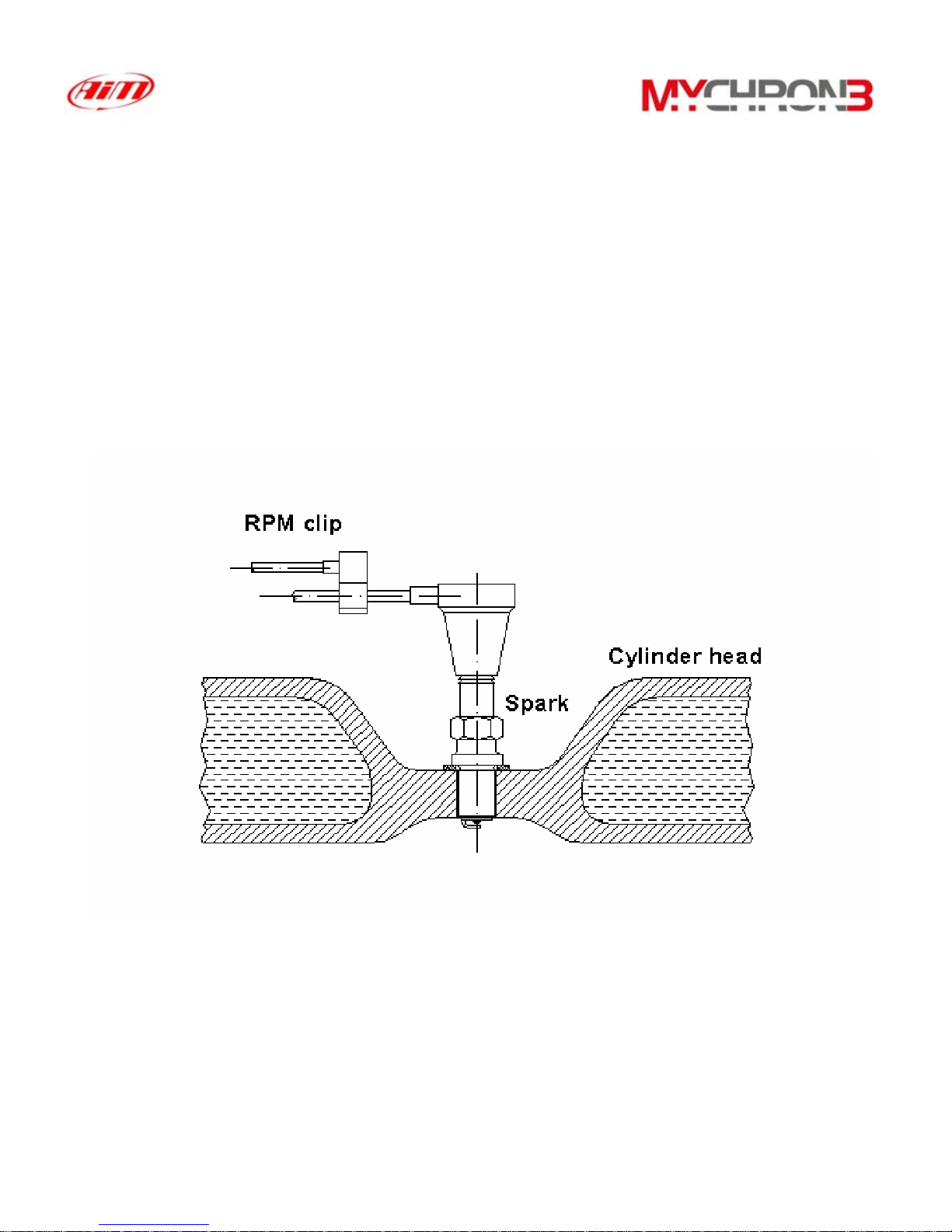
Installing the underspark thermocouple........................................................................20
Connecting cables to MyChron 3 ..................................................................................21
HOW TO USE MYCHRON 3 .................................................................................... 23
Configuration functions.................................................................................................23
Utility functions .............................................................................................................31
Maintenance ..................................................................................................................35
MYCHRON 3AND THE COMPUTER ........................................................................ 36
Software installation......................................................................................................37
Installing the USB drivers .............................................................................................41
CONFIGURATION VIA SOFTWARE .......................................................................... 44
Channels settings...........................................................................................................48
Configuration via “Visualization” pushbutton..............................................................49
Transmitting the configuration to MyChron 3...............................................................50
QUICK REFERENCE GUIDE ..................................................................................... 52
3

Getting Started with MyChron 3
Aim has developed and tested your MyChron 3 to provide precise and
accurate results.
Here are the parts of your system:
•MyChron 3 Display Unit ( 1 ).
•RPM sensor ( 2 ).
•Thermocouple – In alternative you may choose Water Sensor ( 5 ), Exhaust
Gas Sensor ( 9 ) or Underspark Temperature Sensor ( 10 ). The Water
Temperature Sensor may be provided with an M5 connection or a 1/8
connection.
•Optional water thermocouple M5 fitting ( 11 ).
•Thermocouple extension cable ( not shown ).
•Lap Timer . May be optical ( 3 ) or magnetic ( 8 ). The optical one is provided
with the optical transmitter ( 4 ), while the second one may work only in the
kart tracks provided with a magnetic strip.
•External power wire for Infrared transmitter ( 6 ) for IR version.
•Optional USB data download cable ( 7 )
See also Fig. 1.1 on page 5.
4

Fig 1.1 Packing list
Also available
5

MyChron 3 and its parts
Before installing MyChron 3, please read carefully these installation instructions.
It is very important that your MyChron 3 is correctly installed to capture
consistent and accurate data. Incorrect installation may result in system
malfunction.
In the following drawing it is represented MyChron 3 mounted on a kart steering
wheel.
6

The Display
Low battery warning
RPM display
Temperature
Temperature
measure unit
RPM digital display
Night Vision
Lap time
Lap number
The wide display with backlight generally shows RPM, temperature, completed
lap number and, when the kart passes in front of the beacon, it shows the Lap
Time ( or Split Time ). It is also possible to configure a second page ( using button
VIEW ) in order to see RPM digital value ( as showed in the previous drawing ) or
best lap time. When you are not running it is also possible ( using button VIEW )
to see the battery voltage.
The display also presents some small icons, showing the configured Temperature
Measure Unit ( Celsius [°C] or Fahrenheit [°F] ), the Night Vision option and the
Low Battery Warning, that appears when the batteries are down.
Your MyChron 3 has also an automatic power down feature that
turns the power off after 10 minutes of inactivity
7

The Keyboard
off
VIEW
on
q
uit
MEM
ok
USB
>>
MENU
<<
The Keyboard, composed by four push-buttons, is used for turning the power ON
and OFF, configuring the system, recalling the recorded data and clearing the
internal memory.
The four pushbuttons are used for:
MENU/<< Used in configuration to switch to previous option and to turn on
backlight during a test
>> Used in configuration to switch to next option.
MEM Used to CONFIRM a configuration and to retrieve recorded data.
VIEW Used to TURN ON the instrument, to exit configuration menu, or
to switch the display from “digital RPM” value to “battery voltage”
or to “best lap time”
To switch the gauge OFF press at the same time MEM and VIEW
To run the system in DEMO MODE, press button VIEW while holding down
button MENU/<< and >>.
8

The RPM Cable
This clip wire is designed to be plugged directly on the spark plug wire and it is
used for RPM pick up from monocylinder 2-4 stroke engines.
When running the RPM cable along the chassis between the MyChron 3 display
unit and spark plug wire, the RPM cable should be positioned as far as possible
from the thermocouple wire.
9
Table des matières
Manuels Instrument de mesure populaires d'autres marques

Endress+Hauser
Endress+Hauser Proline Promag 50 Caractéristiques techniques

Siemens
Siemens SITRANS F Coriolis FCT030 Manuel de la liste des pièces

KLINGER
KLINGER CMF V Series Manuel utilisateur

EXFO
EXFO FTB-2 Manuel d'exploitation et d'entretien

Keysight
Keysight M8290A Manuel utilisateur

ADTEK
ADTEK MW-5 Manuel utilisateur


