Melink Intelli-Hood Controls Manuel utilisateur

Melink Corporation (513) 527-7020 www.melinkcorp.com
REFERENCE GUIDE
Rev. 1.6


Table of Contents
Section 1: Intelli-Hood Operation and Simplissimo Settings
Section 2: Troubleshooting/ Component Compatibility
Section 3: Drive Connections
Section 4: Drive Programming
Section 5: Helpful Phone Numbers and Contact Information


Section 1:
Intelli-Hood Operation and
Simplissimo Settings

Operation/Service Specifications for Melink Intelli-Hood Operator
1-1
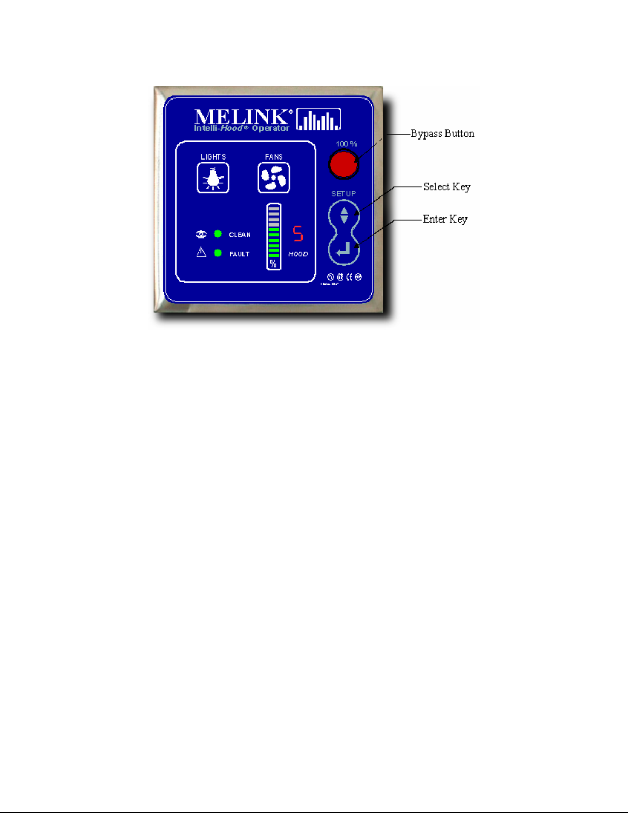
KEYPAD OPERATION
•LIGHTS Button - Turns hood lights on and off if I/O board output is tied into the hood light circuit. Also
turns APU blowers on and off.
•FANS Button - Turns the fans on and off. Also turns APU blowers on and off.
•BYPASS Button - Turns fans on in bypass mode. If the processor is running, then the 7-segment
display will show a 'E' for bypass mode and the bar graph will show VFD speed at 100% (blinking).
Also turns on APU blowers.
•SELECT (up & down arrows)
oIn SETUP mode, this switch will scroll through main menu item numbers (0-9) on the seven-
segment display and scroll through the setup selections on the bar graph.
oIn normal operating mode, this switch will display scrolling temperatures a single time for each
hood on the bar graph; after which it displays scrolling % fan speeds.
•ENTER
oIn SETUP mode, this switch will validate a selection.
oIn normal operating mode, this switch will display average VFD speed on the bar graph.
•To enter SETUP mode, press both the SELECT key and the ENTER key for 10 seconds.
•To restore setup defaults:
oMust be in setup mode.
oMust be at the flashing '0'.
oPress and hold the SELECT key for 10 seconds.
oA 'd' will show on the 7-segment display.
oHold the SELECT key for another 10 seconds.
oDefault data will be stored.
o2 beeps

Operation/Service Specifications for Melink Intelli-Hood Operator
1-2
•To reset average VFD speeds:
oMust be in setup mode.
oMust be at the flashing '0'.
oPress and hold the ENTER key for 10 seconds.
oA 'r' will show on the 7-segment display.
oHold the ENTER key for another 10 seconds.
oAverage VFD speeds will be reset.
o2 beeps
•To lock programming:
oPress and hold the both the SELECT key and the ENTER key for 10 seconds.
oDisplay a flashing '0'.
oPress and hold the both the SELECT key and the ENTER key for 10 seconds.
oA 'L' will show on the 7-segment display
oPress ENTER to exit setup mode
•To unlock programming:
oPress and hold the both the SELECT key and the ENTER key for 10 seconds.
oDisplay 'L'.
oPress and hold the both the SELECT key and the ENTER key for 10 seconds.
oA flashing '0' will show on the 7-segment display
oPress ENTER to exit setup mode
•Program Editing While Locked:
oOnly temperature spans can be changed while programming is in the locked state.
oPress and hold the both the SELECT key and the ENTER key for 10 seconds.
oDisplay 'L'.
oPress the SELECT key. The 'L' display will change to '1' which signifies hood #1.
oTo select a different hood, press the SELECT key. The '1' display will change to '2' which
signifies hood #2. Press SELECT again to change to hood #3 and so on.
oTo edit the temperature span of a particular hood, press the ENTER key when the
appropriate hood number is displayed. The bar graph will light showing the current
temperature span setting. Use the SELECT key to scroll to a different span. Press ENTER
to store the new span. The display will revert back to hood selection.
oTo exit programming, use the SELECT key to scroll to display 'L'. Press ENTER to exit
programming.
•Summer/Winter (3 Gang Coverplates Only)
oThis switch will activate the external heat circuit when closed. It will turn off the external heat
circuit when open.

Operation/Service Specifications for Melink Intelli-Hood Operator
1-3
Simplissimo Settings
Hood Settings
Exhaust Temp Span - This sets up the temperature span for modulating VFD speed between its set
minimum and maximum based on temperature. The span has a low value of 75oF and a maximum of up
to 150oF. Auto Span automatically sets the temperature span based on average VFD speeds over
periods of approximately one day (starting with the 75-110 setting).
Min Speed - This sets up the minimum speed that the VFD will run. Min speed must be less than
maximum speed. DF means that when fans are turned on, the fans will run at 100% for 1 minute and
then return to their normal minimum speed. Maximum minimum speed is 80%.
Max Speed - This sets up the maximum speed that the VFD will run. Max speed must be greater than
minimum speed. Minimum maximum speed is 50%.
Exhaust Temp. Alarm #1 - This sets up the first temperature set point for the 24 VDC exhaust alarm.
Set pt #1 must be less than set pt #2. If the operator tries to set up a set pt #1 greater than or equal to set
pt #2, the error beep will sound. When the setpoint is reached, and the bar graph corresponding to the
hood in alarm will flash and 24Vdc will be sent to the corresponding I/O board terminals. If a setting with
the AUD prefix is selected, then when the hood's speed is being displayed on the bar graph and the
exhaust temperature exceeds the temperature set point #1, the keypad's beeper will sound. The keypad
will go through 12 iterations of beeping the beeper for the alarm.
Exhaust Temp. Alarm #2 - This sets up the second temperature set point for the auxillary 24 VDC
output. Set pt #2 must be greater than set pt #1. If the operator tries to set up a set pt #2 less than or
equal to set pt #1, the error beep will sound. When the setpoint is reached, 24Vdc will be sent to
corresponding I/O board terminals.
No. Hood Sensors - This sets up the number of temperature sensors and optics for the given hood. The
hood can have from 1 to 4 temperature sensors and 1 optics sensor; or it can have from 1 to 4
temperature sensors only; or it can have just 1 optic sensor. Optic Channel 1 is always allocated to Hood
1, Optic Channel 2 is always allocated to Hood 2, and so on. Temperature Channel 1 is always allocated
to Hood 1, Temperature Channel 2 is always allocated to Hood 2, and so on.
Note: It is typically not good practice to connect temperature sensors from different hoods together since
the signal is averaged across all sensors connected to that particular channel, potentially having a
detrimental effect on system response to heat.
Auto Fan On/Off – Sets fans to either turn on or off automatically based on either temperature or a
preset timer (turns fans off after set number of hours). In Heat 0 or Heat 5, system will resume typical
operation when exhaust air temperature of any hood is greater than or equal to 90oF. If exhaust air
temperature is less than or equal to 75oF, while the system is on, the either a signal for either 0% or 5%
will be sent to the VFD. If all hoods are at this level, the system will turn off. Note: when fan button is
pressed, there is a ten minute delay until the temperature sensor becomes active for auto on/off
operation.
Send 4-20mA / 0-10V - This sets up the channel for which the VFD is connected for this hood. If 0, then
there is no VFD for the hood. VFD 1 - VFD 4 are outputs on the master Autocal board. VFD 5 - VFD 8
are outputs on the slave Autocal board. If Multiple is selected, then the VFD signal will follow that of the
previous hood (e.g. If Hood 1 is set up with VFD 1 as the output to its exhaust fan, the Hood 2 may be set
to multiple to follow VFD 1 for the supply fan).
Short Cycle Hood Ratio - This sets up the short cycle hood ratio.

Operation/Service Specifications for Melink Intelli-Hood Operator
1-4
System Settings
Auxiliary VFD Output - This sets up how the signal is determined for the auxiliary VFD output.
•No - No auxiliary output
•Average - send the average of the used VFDs on board.
•Highest - send the highest of the used VFDs on board
•Lowest - send the lowest of the used VFDs on board
•VFD1 - send the same signal that is going to VFD 1
•VFD2 - send the same signal that is going to VFD 2
•VFD3 - send the same signal that is going to VFD 3
•VFD4 - send the same signal that is going to VFD 4
Auxiliary VFD Input - This sets up how the VFDs will respond to the auxiliary 4-20 mA VFD input.
•No - No auxiliary input
•Add - Add aux input to each VFD output
•Sub - Subtract aux input from each VFD output
•Average - Average aux input with each VFD output
Hang Time - Amount of time fans will be left at max speed and smoke alarm will be activated after
detection of smoke.
Relay Input - If #1 (No), then the remote input terminals are used for nothing. If #2 (Remote On/Off),
then the remote input terminals are used for remotely turning the fans on and off. If settings 3 through 5
(3 through 9 on V4.5 chips) are used, then the remote input terminals are used as inputs for a relay.
When this relay is closed then the minimum speed of 50%, 75%, 90%, etc. is used instead of the
minimum speed called out in hood menu #2. The external heat circuit is activated when the relay is
closed. When the relay is open then the minimum speed in hood menu #2 is used and the external heat
circuit is turned off.
Bypass Timer - If item 2 - 10 are selected this sets the bypass timeout. This sets the amount of time to
leave the system in bypass mode after the bypass switch on the front panel is pressed. The dipswitch on
the Autocal II board must be in the bypass timer position. Bypass mode can be turned off by pressing the
bypass switch again. If item 1 is selected then bypass mode can only be turned off by pressing the
bypass switch again.
Comfort Mode - When the comfort mode is enabled: if kitchen temperature is > 75 and outside
temperature < 75, then the VFD speed is increased up to max speed with a ramp of 1 minute. If the
kitchen temperature cools to < 70 or the outside temperature increases to >75, then reduce the VFD
speed back to automatic control. The kitchen and outside temperature sensors can be wired to the I/O
board terminal block (item #3) or to Temp #3 (kitchen) and Temp #4 (outside) (selection #4). Selection #1
and #2 will disable the comfort mode. Selection #2 will allow the MUA temperature sensor to be wired to
Temp #4 for short cycle hoods.
Miscellaneous - If item #1 is selected then there are no miscellaneous functions enabled.
•Win SB (item #2) - If kitchen temperature is less than or equal to 70, then the temperature
span automatically increases to the next higher range. If the kitchen temperature is greater
than 75, then the temperature span automatically revert back to original set point.
•Int Bar (item #3) - The bargraph displays the speed that the system is sending to the drive
instead of reading the speed from the drive. This will disable the VFD fault capability.
Alarm #2 Output - This sets up the function of the auxiliary 24 VDC output.
•Temp - Output is used as temperature set point #2 alarm.
•Smoke - Output is used as a smoke alarm.
•Starter - Output is used as control for a magnetic motor starter. The motor starter is turned
on if any of the exhaust temperatures exceed 90oF or smoke is detected or BYPASS mode is
Autres manuels Melink Système de contrôle


