Maxol SUPACOMBI HE28 Manuel utilisateur

SUPACOMBI HE28
USER INSTRUCTIONS
TO BE GIVEN TO THE USER
G.C. Appliance No. 47-260-12
0086
Pin 87/BR/93
The Maxol Supacombi HE 28 is a high efficiency condensing, fully
automatic, wall mounted, fan-assisted, balanced flue gas combination
appliance suitable for room sealed applications, for use with natural gas.
This combination appliance provides the user with both central heating
(CH) and domestic hot water (DHW) on demand.
The Supacombi HE 28 provides central heating and domestic hot
water at outputs between 12.1 kW (41,300BTU/h) and 28.3 kW
(96,600 BTU/h).
Heat output is controlled according to demand (in both domestic hot
water and central heating modes) by the fully modulating pre-mix burner
control. The appliance always gives priority to domestic hot water supply.
The appliance incorporates frost protection. The main electrical supply to
the appliance must, however, not be isolated for this to be operational.
An electro/mechanical 24hr time clock is fitted as standard.
Gas Consumer Council
The Gas Consumer Council (GCC) is an independent organization which
protects the interests of gas users. If you need advice, you will find the
telephone number in your local directory under 'Gas'.
2
SAFETY
Read these instructions and the user label (fitted on the boiler front panel)
carefully before attempting to operate the appliance. Comply with all
applicable warnings.
Do not interfere with any sealed
components and use the appliance only in accordance with
these instructions.
CURRENT GAS SAFETY (INSTALLATION AND
USE) REGULATIONS OR THE RULES IN FORCE.
It is the law that all gas appliances are installed by a competent person in
accordance with the above regulations. Failure to install appliances
correctly could lead to prosecution. It is in your own interest, and that of
safety, to ensure that the law is complied with.
If the appliance is damaged, turn off the appliance and consult a CORGI
registered installer.
If it is known or suspected that a fault exists on the appliance it MUST
NOT be used until the fault has been rectified by a competent person.
2.2
ELECTRICAL SUPPLY
This appliance must be earthed.
Supply: 230V ~ 50Hz fused at 3A.
The method of connection to the mains supply must facilitate complete
isolation of the appliance. Either a 3A fused three pin plug and
unswitched shuttered socket outlet, or a 3A fused double pole switch
having a 3 mm contact separation in both poles, serving only the boiler
(and its external controls), may be used.
2.3
CLEARANCES AND VENTILATION
It is not necessary to have a purpose provided air vent in the room or
internal space in which a room-sealed appliance is installed. Cupboard
or compartment ventilation is not necessary for a room-sealed appliance
providing that the minimum clearances are maintained.
1
INTRODUCTION
3
BOILER LOGBOOK
Please ensure that the Benchmark Logbook supplied with the installation
instructions of your appliance is completed by your installer to verify that
the correct installation and commissioning procedure was followed.
Failure to complete the Logbook may result in difficulties should a
problem arise with your appliance during the guarantee period.
This Logbook forms part of the industry's Benchmark code of practice for
the installation, commissioning and servicing of central heating systems.
All CORGI Registered Installers carry a CORGI ID card and have a
registration number. Both should be recorded in your Logbook.
You can check your installer is CORGI registered by calling CORGI on
0870 401 2230.
On a demand for DHW, water flow is detected and the ignition
sequence initiated. The fan and pump will start and the boiler will light.
If the DHW draw off rate is high (over 10l/min.), the appliance will run
continuously at full output until the tap is either turned off, or the flow rate
is reduced, in which case the heat supplied will reduce accordingly to
maintain a steady temperature (60°C max).
Hot water is made available at the appliance outlet almost immediately,
but the final temperature and time taken for the hot water to reach a tap
depends upon the rate at which water is drawn off and the length of the
pipe runs between the boiler and taps.
When the tap is turned off, the appliance after a short period of time will
revert to central heating mode if there is a demand. Otherwise the
burner will be extinguished until the next demand for hot water.
Priority is always given to Domestic Hot Water supply.
2.1
4
HOT WATER OPERATION
Switch on the electrical supply.
1) To adjust the timer to the current time of day, simply rotate the outside
edge of the clock, clockwise to line up with the current time on the 24
hr clock dial.
2) To set the CH to come on at a specific time, slide out the small tabs
around the outside edge of the timer, for the duration you would like
the CH to be active. For instance – To activate the central heating
between 6am and 9am, slide out all the tabs between the 6 and 9.
To activate the central heating between 5pm and 10pm, slide out all
the tabs between the 17 and 22. The boiler can be set to switch on
and off at intervals of 15 minutes, as many times as required per day.
3) Set the clock override switch to the TIMED position (middle setting)
which is marked as . The CH will now be active during the time
periods set.
4) If the clock override switch is set to
I
the timer will activate the CH
continuously, and if it is set to
0
, the timer will turn the CH off.
5) The mechanical timer has no effect on the supply of DHW.
SETTING THE CLOCK AND TIMER
5.1
5
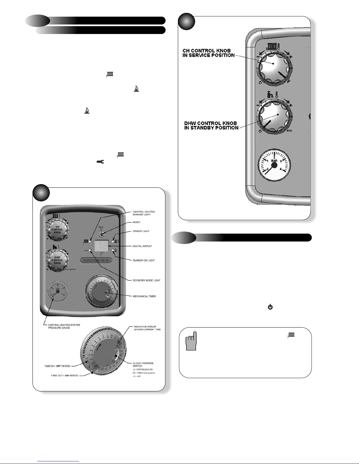
OPERATING INSTRUCTIONS
Refer to Fig. 1
Note: After a hot water draw off the burner may
stay on for a few seconds (see clause 5.8 'Keep
hot facility' in the installation manual)
1) If heating is required, ensure that the clock is set to an ON period
(see diagram) or set the clock over-ride switch to the ON position.
Turn up the room thermostat (if fitted).
2) Turn the control knob to the midpoint between minimum and
maximum setting. The digital display changes to the temperature
setpoint in °C, and the CH demand light will illuminate.
3) When the burner has lit the digital display changes to the boiler
temperature to indicate heating ON and the flame light will
illuminate.
4) Hot water will be supplied as soon as any Domestic Hot Water tap
is turned on. The flame light will illuminate.
5) If the burner fails to light the fan will stop. Initially this may be due to
air in the gas supply. The boiler will automatically have five attempts
at ignition.
6) After the five attempts it may be necessary to RESET the boiler by
pressing the RESET button.
7) If at any time the central heating demand and ECO lights flash,
the product is in service mode (full clockwise). To remove from
service mode, turn the CH control knob back to a position between
1 and 10.
TO LIGHT THE BOILER IN CENTRAL
HEATING MODE
5.2
DHW:Hot water temperature is adjustable between 40 and 60°C.
CH:Adjustable via the CH temperature control knob to give radiator
temperatures of between 40°C and 80°C. To operate the boiler more
efficiently it is recommended that the CH temperature is set to about 6
on the dial.
Note: To select the Economy DHW control, i.e. without DHW preheat,
turn the DHW temperature control knob fully clockwise and then back to
the desired temperature setting. The ECO light will illuminate.
To avoid setting the control knob temperature to in summer when
CH is not required, switch the clock over-ride switch to the OFF position
OR turn the room thermostat off.
CONTROL OF WATER TEMPERATURE
5.3
Note: If the digital display shows flashing
and ECO lights the boiler is in service mode and
the boiler will fire continuously at minimum input.
(See fig.2)
This setting is for the convenience of the
Service Engineer ONLY.
2
1
SERVICE HELPLINE: 01926 834834
Maxol Boilers, 20-22 First Avenue,
Bluebridge Industrial Estate, Halstead, Essex, CO9 2EX
Tel: 01787 272800 Sales: 01787 475557 Fax: 01787 474588
Te chnical/Service: 01926 834834 Training: 01926 834838
www.maxolboilers.co.uk
Maxol Boilers are manufactured in the UK by Halstead Boilers Ltd, part of the Glen Dimplex Group.
Halstead Boilers is continuously improving its products and may therefore change specifications without prior notice.
The statutory rights of the consumer are not affected.
Refer to Fig. 1
If the digital display shows an error code between
1
-
5
,
24
and
41
the
boiler is in lockout condition.
To RESET the boiler press the RESET button.
All other error codes are blocking codes which can not be RESET.
For detailed fault finding, refer to the diagnostic chart in the installation
manual, together with the notes given in sections 8.3, 8.4 and 8.5 of the
boilers installation manual.
DIAGNOSTIC DIGITAL DISPLAY
5.6
The pressure gauge on the control fascia panel indicates the central
heating system pressure. If the normal running pressure is seen to
decrease from the original installation pressure of around 1 bar (cold)
over a period of time, then there may be a water leak. In this event
consult a CORGI registered installer.
Do not attempt to fire the boiler if the pressure has reduced
to zero from the original setting.
PRESSURE GAUGE
5.7
The front panel, being a powder coated white finish should be cleaned
with a damp cloth and mild detergent. Do not use abrasive cleaners.
GENERAL CARE
6
To ensure continued efficient operation of the appliance, it is recommended
that it is checked and serviced as necessary at regular intervals. The
frequency of servicing will depend upon the particular installation
conditions and usage but in general once a year should be adequate. It is
law that any service work must be carried out by a competent person such
as British Gas or other CORGI registered personnel.
ROUTINE SERVICING
7
Like all condensing boilers this appliance will produce a plume of
condensation from the flue terminal. This is due to the high efficiency and
low flue gas temperature of the boiler. It is normal and not a fault.
PLUMING FROM TERMINAL
9
If a gas leak is suspected or exists, turn the gas OFF at the
incoming mains (adjacent to the meter). Do not operate any
electrical switches. Do not operate any electrical appliances.
Open all windows and doors. Do not smoke. Extinguish all
naked lights. Phone the Transco 24 hour emergency number
immediately on 0800 111 999. (Do not call from a mobile
phone).
The boiler is fitted with a condensate trap.
The condensate drain point must not be modified or blocked
(see section 4.6 of the installation manual).
WARNING
8
For short or long periods
Switch the programmer and/or room thermostat switch to the OFF
position.
Note: The appliance is fitted with a frost protection device. In the event
of very cold conditions, the pump may operate and the boiler light for a
few minutes to protect the appliance from potential frost damage. This
can only function if the gas and electricity supplies are maintained and
the control knobs on the appliance are set to the ‘STANDBY’
position.
This function automatically operates the boiler when the heating system
water reaches temperatures below 5°C.
If either the gas or electricity services are to be isolated during a period
when frost is likely, the water circuits must be drained.
TO TURN THE BOILER OFF
5.4
The appliance is fitted with two water temperature overheat controls. In
the event of overheating, the boiler will shut down and the digital display
will show '1'.
Allow the boiler to cool, then press the RESET button.
If the fault persists, consult a CORGI registered installer.
BOILER OVERHEAT PROTECTION
5.5
03/07- 751155
Autres manuels pour SUPACOMBI HE28
1
Autres manuels Maxol Chaudière

Manuels Chaudière populaires d'autres marques

Vaillant
Vaillant uniSTOR VIH SW GB 500 BES Manuel utilisateur

Radijator
Radijator BIO max 23.1 Manuel utilisateur

Brunner
Brunner BSV 20 Manuel utilisateur

Buderus
Buderus Logamax GB062-24 KDE H V2 Manuel utilisateur

Potterton
Potterton 50e Fiche technique

UTICA BOILERS
UTICA BOILERS TriFire Manuel utilisateur


