MARTINS Industries MFJ-PL2T Manuel utilisateur

MARTINSINDUSTRIES.COM
MANUAL
2T & 3T PROFESSIONAL
FLOOR JACKS
MFJ-P2T
MFJ-P3T
MFJ-PL2T

ENGLISH 01
FRANÇAIS 06
ESPAÑOL 11
DEUTSCH 16

TABLE OF CONTENT WARRANTYTABLE OF CONTENT
P. 02 Safety
P. 02 Assembly
WARRANTY
P. 01 Warranty
P. 01 Specifications
ENGLISH | 01
MFJ-P2TModel
2 000 kg
Maximum load capacity
Lifting Range
4 409 lb
SPECIFICATIONS
This product includes a 3-years warranty from the billing date, but is null and void if the product has been damaged
through misuse, improper maintenance or accidental damage, or unauthorized modifications or repairs.
WARRANTY
P. 03 Operations
P. 04 Maintenance
P. 05 Troubleshooting
3 000 kg 6 614 lb
2 15/16" - 19 11/16"
75 - 500 mm 3 3/4" - 19 11/16"
95 - 500 mm
RUBBER PAD
TRAY
(REMOVE TO ACCESS
OIL FILL PLUG)
SADDLE
HANDLE
PROTECTIVE
HANDLE SLEEVE
LIFT ARM
75 - 530 mm 2 15/16" - 20 7/8"
PEDAL
3
YEARS
MFJ-P2T
US / CANADA
2 Metric Ton 2.2 US Ton
MFJ-P3TMFJ-P3T
US / CANADA
3 Metric Ton 3.3 US Ton
MFJ-PL2T
2 000 kg 4 409 lb
MFJ-PL2T
US / CANADA
2 Metric Ton 2.2 US Ton

02 |ENGLISH
SAFETY
BEFORE using this product, read this manual and follow all its Safety and Operating instructions.
Failure to do so may result in personal injury and/or property damage.
Retain these instructions for future reference.
Inspect before each use. Do not use if broken, bent, cracked or damaged parts (including labels) are noted.
Do not modify or use this product for any other application than what it has been designed for.
Lifting device only, always use Jack Stands to support the vehicule before working.
ASSEMBLY
STEPS
12
3
6-8
Assemble the 2 parts of
the lifting arm together. Insert into the lift arm socket and
tighten the bolt to lock the lifting
arm in place.
Prior to operating floor jack:
• Turn the lifting arm counterclockwise.
• Pump the jack several times
(6 to 8 full strokes) to ensure
internal lubrification and
eliminate air from the system.
Repeat if needed.

ENGLISH | 03
OPERATIONS
The floor jack is not designed to maintain heavy loads for long period of time. Do not place any parts of body under
the load without jacks stands in place. Before lowering the load, ensure that there no obstructions underneath and
that all people are standing clear.
PRIOR TO LIFTING
1. Set the parking gear and engage the parking brake.
1.1 Vehicle with manual transmission.
1.1.1 Engage the parking brake and leave the car in reverse or 1st gear. (refer to vehicule owner’s manual).
2. Turn counterclockwise to release to the initial position.
3. Center jack saddle under lift point. (refer to vehicule owner’s manual)
4. Pump lifting arm until reaches desired height.
5. Transfer the load to Jack stands.
LOWERING
1. Raise load with floor jack high enough to clear the jack stands.
2. Carefully remove the jack stands.
3. Turn counterclockwise, until initial position.
4. Always remove the floor jack once the load is on the ground.
Only use this device once you have read the
instruction manual and / or have been trained
by your employer. The product should only
be used to lift vehicules within the maximum
load capacity.
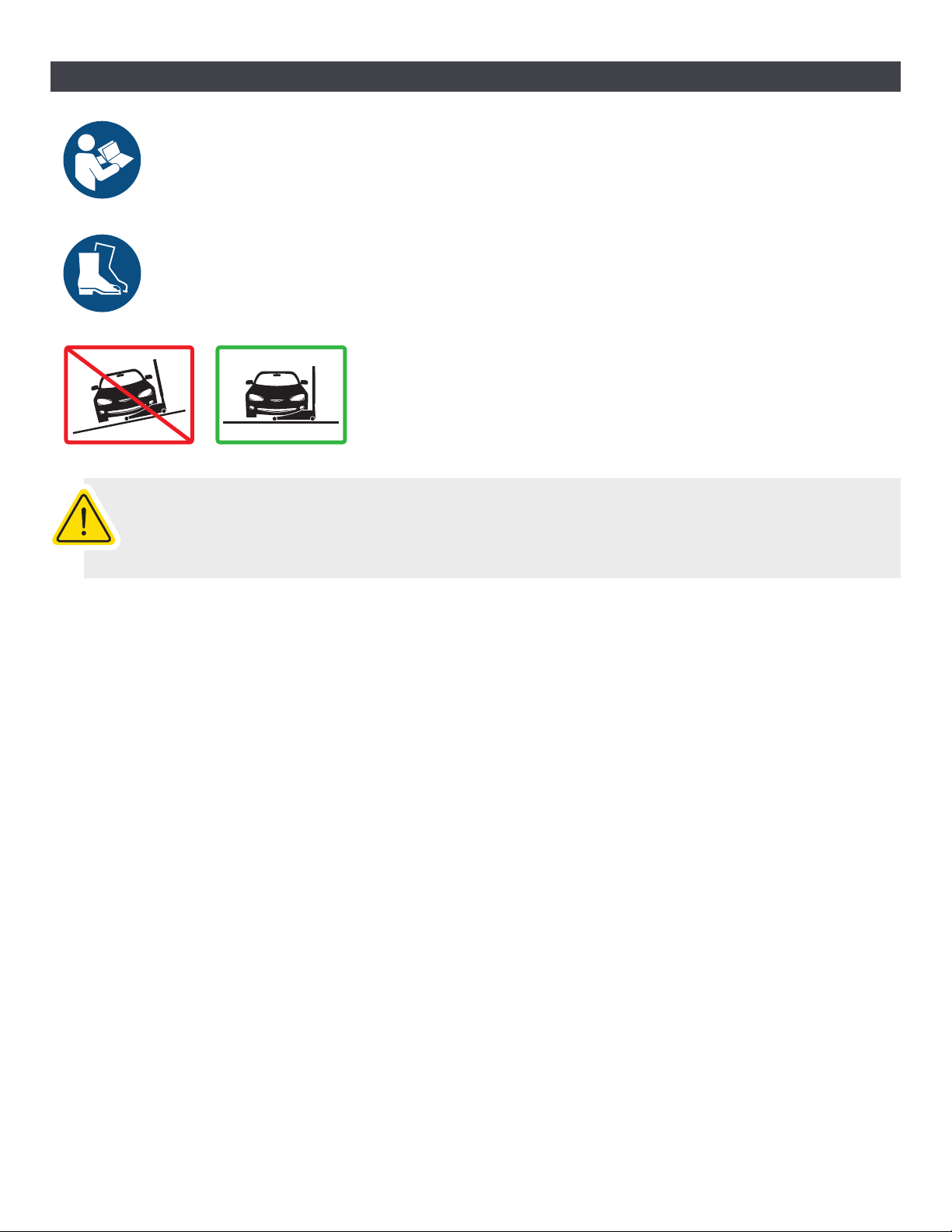
Always use on a stable and level surface.
Always check the stability of the vehicle before use, to prevent injuries
and/or damages.
Do not exceed maximum load capacity.
Wear safety boots while using the device.

04 |ENGLISH
MAINTENANCE
The owner and/or operator must be aware that the use and maintenance of this product may require
special skills and knowledge.
Use only high-grade hydraulic jack oil and avoid mixing different types of fluid. Improper fluid can cause failure,
immediate loss of load, damages and/or injuries.
MONTHLY MAINTENANCE
Monthly cylinder lubrification and pumping mechanism maintenance is recommended, only use light oil.
Be aware that any dirt, rust, etc. can damage the internal components.
YEARLY MAINTENANCE
For best performance and longest product life, hydraulic jack oil needs to be changed, at least once a year.
ADDING OIL
1. With saddle fully lowered.
2. Remove the oil filler plug.
3. Fill, until oil reached the lower rim of the oil plug.
4. Reinstall oil filler plug.
5. Follow BLEEDING AIR procedure.
REPLACING/CHANGING OIL
1. Fully lower the saddle.
2. Remove the oil filler plug.
3. Lay the floor jack on its side.
4. Drain the fluid into a suitable container.
5. Fill with new oil, until it reached the lower rim of the oil plug.
6. Reinstall oil filler plug.
7. Follow BLEEDING AIR procedure.
NOTE: Disposal of hydraulic oil fluid should been always done in accordance with your local regulations.
BLEEDING AIR
1. Open the release valve by turning the lifting arm counterclockwise.
2. Pump for 6 to 8 full strokes to eliminate any air in the system.
3. Open oil filler plug to allow the trapped air to escape.
4. Close back the oil filler plug.
Note: Before putting into use, always test several times for proper operation.
Repeat if necessary.
OIL
FILLER
PLUG

ENGLISH | 05
SOLUTIONS
POSSIBLE CAUSES
PROBLEMS
TROUBLESHOOTING
Floor Jack will not lift load
Floor Jack not lifting to full extension Not enough hydraulic jack oil Refer to ADDING OIL procedure
Air trapped in the hydraulic system Refer to BLEEDING AIR procedure
Refer to BLEEDING AIR procedure
Load is too heavy Consider higher capacity floor jack
Floor Jack not lowering completely Too much hydraulic jack oil Refer to REPLACING/CHANGING OIL
procedure
Air trapped in the hydraulic system

TABLE OF CONTENT WARRANTYTABLE DES MATIÈRES
P. 07 Sécurité
P. 07 Assemblage
WARRANTY
P. 06 Garantie
P. 06 Spécifications
SPÉCIFICATIONS
Le produit est assujetti à une garantie de 3 ans à compter de la date de facturation, mais la garantie est non
valide si le produit a été endommagé à la suite d'une utilisation abusive, a été mal entretenu, a été endommagé
accidentellement ou a été modifié / réparé sans autorisation.
GARANTIE
P. 08 Opérations
P. 09 Entretien
P. 10 Dépannage
06 |FRANÇAIS
PATIN CAOUTCHOUC
PLATEAU
(ENLEVER POUR ACCÈS
AU BOUCHON HUILE)
SELLE
POIGNÉE
MANCHON
PROTECTEUR
POIGNÉE
DE LEVAGE
PÉDALE
3
YEARS
MFJ-P2TModèle
2 000 kg
Capacité de levage
maximum
Levée
4 409 lb 3 000 kg 6 614 lb
2 15/16" - 19 11/16"
75 - 500 mm 3 3/4" - 19 11/16"
95 - 500 mm 75 - 530 mm 2 15/16" - 20 7/8"
MFJ-P2T
US / CANADA
2 Metric Ton 2.2 US Ton
MFJ-P3TMFJ-P3T
US / CANADA
3 Metric Ton 3.3 US Ton
MFJ-PL2T
2 000 kg 4 409 lb
MFJ-PL2T
US / CANADA
2 Metric Ton 2.2 US Ton

SÉCURITÉ
AVANT d'utiliser ce produit, veuillez lire et suivre toutes les consignes de sécurité et de
fonctionnement du présent guide. Tout manquement à ces directives peut entraîner des
blessures corporelles ou des dommages matériels.
Conserver le Manuel d’instructions à des fins de consultation future.
Inspecter avant chaque utilisation. Ne pas utiliser l’appareil si des pièces brisées, tordues, fissurées ou endommagées sont
signalées (y compris les étiquettes).
Ne modifiez ou n’utilisez pas ce produit pour un autre usage pour lequel il a été conçu.
Cet appareil doit servir uniquement au levage. Toujours utiliser des chandelles pour supporter le véhicule avant de travailler
sous celui-ci.
ASSEMBLAGE
ÉTAPES
12
3
6-8
Assembler les 2 parties
du bras de levage. Insérer la poignée de levage
à l’endroit spécifié et serrer
le boulon pour verrouiller en place.
Avant l’utilisation du cric le levage:
• Tourner le bras de levage sens anti-horaire.
• Pomper plusieurs fois
(6 à 8 coups complet)
afin d’assurer la lubrification interne et
purger l’air du system.
Répéter au besoin.
FRANÇAIS | 07
OPÉRATIONS
Le cric de levage n’est pas conçu pour supporter la charge du véhicule sur une longue période de temps.
En aucun temps, se placer sous le véhicule avant qu’il ne soit soutenu par des chandelles. Avant d’abaisser
la charge, s’assurer qu’il n’y ait pas d’obstacles et que toutes les personnes se tiennent à l’écart.
LEVAGE
Avant de lever le véhicule :
1. Mettre le bras de vitesse en position
Park
(Stationné) et enclencher le frein à main.
1.1. Pour les véhicules à transmission manuelle :
1.1.1 Activez le frein à main et mettre en position
Reverse
(Reculer) ou enclencher en 1ère vitesse
(consulter le Manuel d’utilisation du véhicule).
2. Tourner dans le sens anti-horaire pour mettre en position initiale.
3. Centrer la selle du cric sous le point d’appui du véhicule.(consulter le Manuel d’utilisation du véhicule).
4. Actionner le bras de levage jusqu’à la hauteur désirée.
5. Transférer la charge sur des chandelles.
ABAISSEMENT
1. Soulever suffisamment la charge à l’aide du cric afin que celle-ci qu’elle ne repose plus sur les chandelles.
2. Retirer les chandelles prudemment.
3. Tourner doucement afin de mettre en position initiale.
4. Toujours enlever le cric lorsque la charge est complètement au sol.
Utiliser ce produit seulement après avoir lu
le guide d'utilisation et/ou avoir reçu une
formation de votre employeur. Ce produit
doit uniquement être utilisé pour le levage
du véhicule en dessous de la capacité maximale.
Porter des bottes de sécurité lors
de l’utilisation de ce produit.
Toujours utiliser sur une surface stable et à niveau.
Toujours vérifier la stabilité du véhicule avant l’utilisation.
Ne pas excéder la capacité maximale de levage.
08 |FRANÇAIS
Ce manuel convient aux modèles suivants
2
Table des matières
Langues :
Autres manuels MARTINS Industries Jack


Manuels Jack populaires d'autres marques


VEVOR
VEVOR TJD-12000SP-F Manuel utilisateur

ULTIMATE SPEED
ULTIMATE SPEED URW 2 A1 HYDRAULIC TROLLEY JACK Manuel utilisateur

Stels
Stels 51131 Manuel utilisateur

Bushranger
Bushranger RJX01 Manuel utilisateur

Clarke
Clarke CTJ2500QLG Manuel d'installation et d'exploitation

Valex
Valex 1650520 Manuel utilisateur


