Magnetek 05P00090-279 Manuel utilisateur

ARCNET Active Hub
Part No. 05P00090-0279
For use on MicroTrac Local Area Network
RD 90-279 © 1997 MagneTek, Inc. 97-04

© 1997 by
MagneTek
New Berlin, Wisconsin
All rights reserved. No part of this publication may
be reproduced or used in any form by any means –
graphic, electronic, or mechanical, including
photocopying, recording, taping, or information
storage and retrieval systems – without written
permission of the publisher.
MicroTrac, DSD, PAC and MagneTek are trademarks of MagneTek, Inc.
Revision History
The following table shows pages that have been revised since the first release of
this document.
Date Affected Pages
4/23/97 First release; supersedes RD 90-297 dated 11/27/95
RD 90-279 © 1997 MagneTek, Inc. 97-04

i
Table of Contents
4/23/97
Table of
Contents Page
Warranty ............................................................................................................ ii
INTRODUCTION ............................................................................................. 1
INSTALLATION ............................................................................................... 3
LAN CABLING RULES AND GUIDELINES ............................................. 4
MASTER - SLAVE CONFIGURATION ....................................................... 6
OPERATION ..................................................................................................... 8
RD 90-279 © 1997 MagneTek, Inc. 97-04
ii Warranty
4/23/97
Warranty Standard products manufactured by the Company are warranted to be free from
defects in workmanship and material for a period of one year from date of
shipment and any products which are defective in workmanship or material will
be repaired or replaced, at the Company's option, at no charge to the Buyer. Final
determination as to whether a product is actually defective rests with the
Company. The obligation of the Company hereunder shall be limited solely to
repair or replace, at the Company's discretion, products that fall within the
foregoing limitations, and shall be conditioned upon receipt by the Company or
written notice of any alleged defects or deficiency promptly after discovery and
within the warranty period, and in the case of components or units purchased by
the Company, the obligations of the Company shall not exceed the settlement
that the Company is able to obtain from the supplier thereof. No products shall
be returned to the Company without its prior consent. Products which the
Company consents to have returned shall be shipped prepaid f.o.b. the
Company's factory. The Company cannot assume responsibility or accept
invoices for unauthorized repairs to its components, even though defective. The
life of the products of the Company depends, to a large extent, upon the usage
thereof, and THE COMPANY MAKES NO WARRANTY AS TO FITNESS
OF ITS PRODUCTS FOR THE SPECIFIC APPLICATIONS BY THE BUYER
NOR AS TO PERIOD OF SERVICE UNLESS THE COMPANY
SPECIFICALLY AGREES OTHERWISE IN WRITING AFTER THE
PROPOSED USAGE HAS BEEN MADE KNOWN TO IT.
This warranty does not apply to experimental or developmental products for
which NO warranty is made or given and Buyer waives any claim thereto.
THE FOREGOING WARRANTY IS EXCLUSIVE AND IN LIEU OF ALL
OTHER WARRANTIES, EXPRESSED OR IMPLIED, INCLUDING, BUT
NOT LIMITED TO, ANY WARRANTY OF MERCHANTABILITY OR OF
FITNESS FOR A PARTICULAR PURPOSE AND BUYER HEREBY
WAIVES ANY AND ALL CLAIMS THEREFORE.
IN NO EVENT SHALL THE COMPANY BE LIABLE FOR LOSS OF
PROFIT, INDIRECT, CONSEQUENTIAL OR INCIDENTAL DAMAGES
WHETHER ARISING OUT OF WARRANTY, BREACH OF CONTRACT OR
TORT.
RD 90-279 © 1997 MagneTek, Inc. 97-04

INTRODUCTION
1
INTRODUCTION
4/23/97
INTRODUCTION The ARCNET Active Hub is an electronic bi-directional repeater designed to
expand the number of ARCNET nodes that can be used on a single network. A
network node is any attached device that can participate in the token-passing
process. Nodes can be drives, PLC gateways, remote display controllers, remote
logic nodes, remote computers, etc.
The ARCNET Hub receives messages sent by any one transmitting node, and
relays the message to all other nodes on the network. The ARCNET Hub has
four ports. Each port can accommodate a cable segment containing up to eight
(8) nodes. The ARCNET Hub also has LED indicators on the Hub card showing
which port LAN segments are actively receiving. The ARCNET Hub card can
be used in a separate power supply/card cage as a stand alone unit, or installed
into a PLC gateway.
RD 90-279 © 1997 MagneTek, Inc. 97-04
INTRODUCTION
2INTRODUCTION
4/23/97
RD 90-279 © 1997 MagneTek, Inc. 97-04
INSTALLATION
3
INSTALLATION
4/23/97
WARNING
It is extremely important that when you work with the ARCNET
Active Hub you avoid static electricity. Static electricity will cause
severe damage to the system’s electrical components. Always ground
yourself by wearing a wrist or ankle strap. When not in use, keep the
ARCNET Active Hub in its anti-static bag.
1. Remove the cover of the MicroTrac DSD PLC Gateway.
2. Remove the Hub Card from its protective anti-static bag. See Warning.
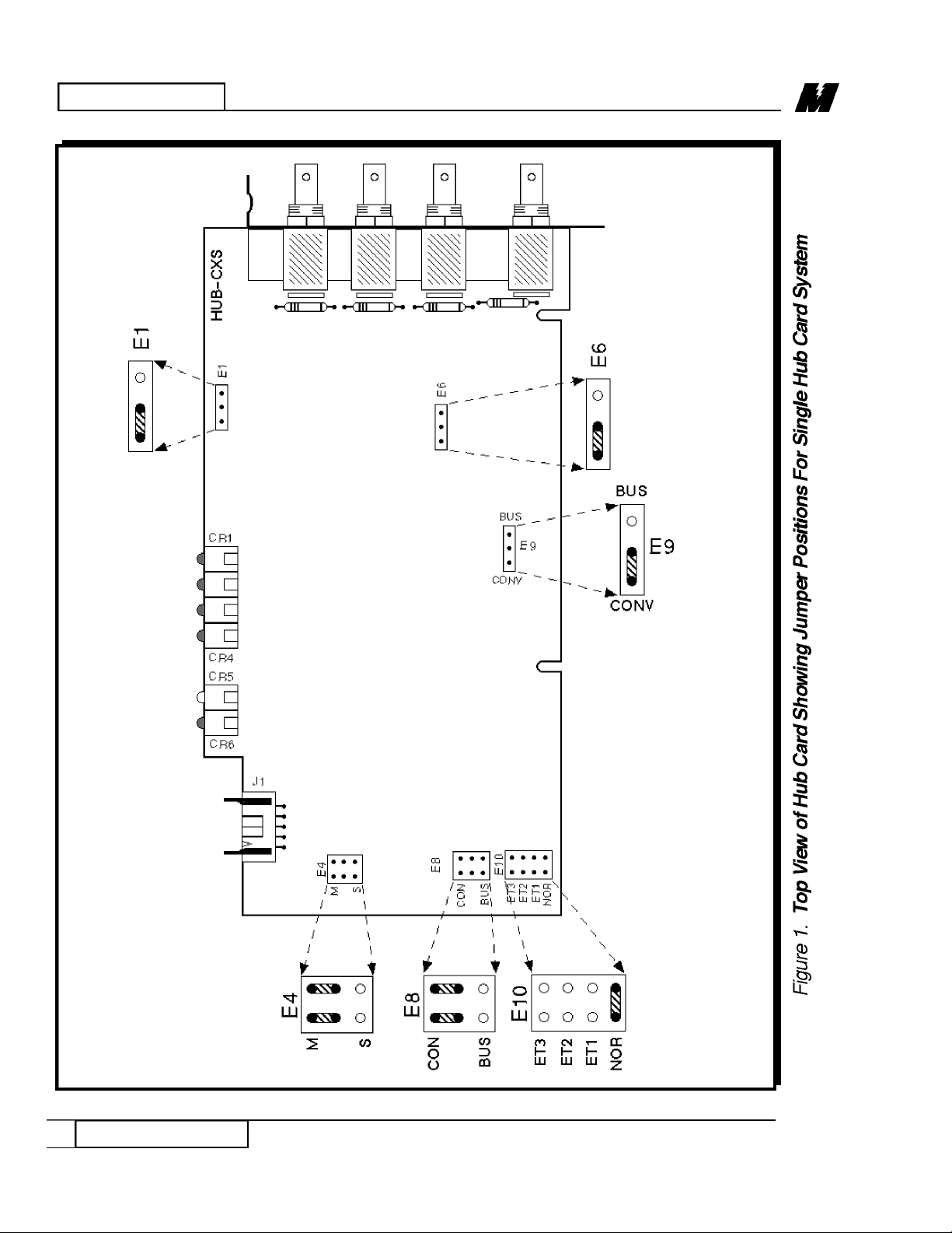
3. Before proceeding, verify all jumper positions shown in Figure 1.
4. Install the Hub Card in an empty slot of the PLC Gateway.
5. Secure the Hub Card with a 6-32 metal screw and a star washer.
6. Important Note: Read “LAN Cabling Rules and Guidelines”.
The ARCNET Hub stand alone unit comes ready to be mounted on a panel. It is
recommended that the stand alone unit be firmly grounded through the chassis,
as well as the power cord. This can be accomplished by first scraping away
paint on the panel around at least one of the chassis mounting holes. Next mount
the assembly using star washers on the mounting bolts. It is also recommended
that the ARCNET Hub be installed away from high power equipment with
devices of similar function (PLC gateways, metering equipment). This is to
prevent noise interference.
Important Note: Verify the jumper positions (see Figure 1), and read “LAN
Cabling Rules and Guidelines” before installation or operation.
INSTALLATION
Installation Into
a PLC Gateway
Stand Alone
Unit
RD 90-279 © 1997 MagneTek, Inc. 97-04

LAN CABLING RULES AND GUIDELINES
4
4/23/97
LAN CABLING RULES AND GUIDELINES
The ARCNET LAN uses RG-62A/U coaxial cable, BELDEN number 9269 or
equivalent (MagneTek Part No. 05P00211-0047). Other cable types will not
work properly.
The LAN cable should be routed with signal level wires only. The LAN cable
may cross power wiring, but only at a 90 degree angle. A LAN cable that runs
parallel to power wiring may pick up noise from that power wiring even if
separated by a space of several inches. It is best to separate signal level wiring
(including the LAN cable) from power wiring (including relay coil wiring) with
a metal divider in a cable tray or by routing the signal wire through its own
metal conduit.
LAN nodes may be connected in any order. Minimum cable length between
nodes is 6 feet, and the minimum bend radius of the cable is 2.5 inches. The
maximum distance from one end of the LAN to the other without the Active
Hub is 900 feet. The ARCNET Active Hub can support a maximum of 900 feet
on each of its 4 ports. A maximum of eight (8) nodes can be connected to each
Active Hub port.
Each LAN node is directly connected to the coaxial cable with a TEE connector
(MagneTek Part No. 05P00034-0540). Both ends of the coaxial cable must be
terminated with a 93 ohm termination (MagneTek Part No. 05P00034-0586).
The ARCNET Active Hub provides its own active termination as long as power
is applied to it. No TEE connector should be used on the Hub ports. The
ARCNET Active Hub must be connected at the end of the coaxial cable. Leave
unused ports open; it is not necessary to terminate them with 93 ohm
terminators.
If a node is disconnected at a TEE connector, either replace the TEE connector
using a BNC-BNC splice or (if temporary for diagnostic purposes) leave it open.
Do not add another 93 ohm terminator, as it may overload the signal and destroy
communications.
The outer conductor of the LAN cable must not touch ground. This means that
cable TEE connectors and terminating resistors should not touch a drive chassis
or any other grounded surface. If cable splice connectors are used for wiring
convenience, they must be insulated from metallic conduit or pull boxes.
LAN CABLING
RULES AND
GUIDELINES
RD 90-279 © 1997 MagneTek, Inc. 97-04
LAN CABLING RULES AND GUIDELINES
5
4/23/97
LAN CABLING RULES AND GUIDELINES
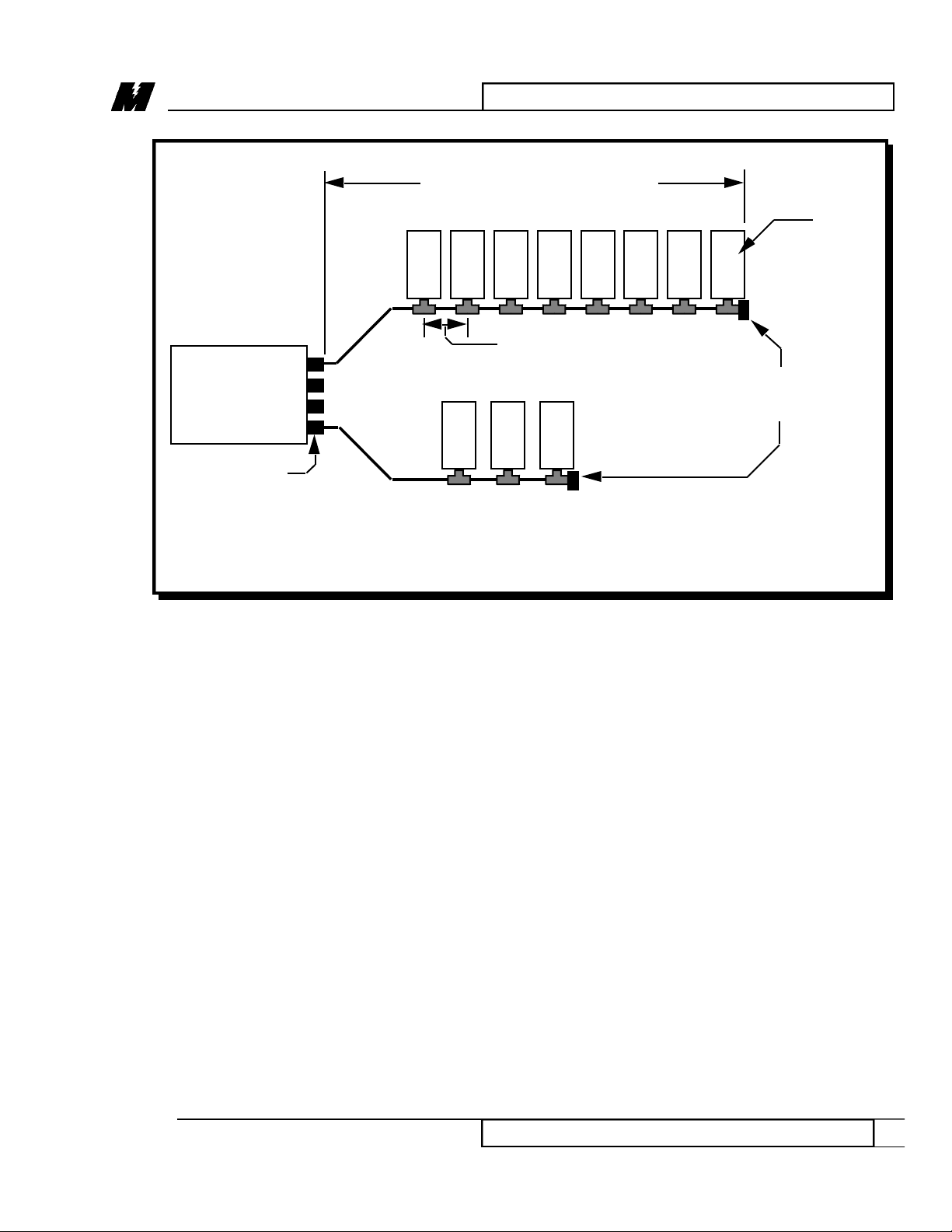
Figure 2. MicroTrac DSD LAN Cabling
HUB
CARD
Length between nodes
(See Note below)
Node
Terminators
(93 Ω)
Port
ARCNET LAN SEGMENT
(See Note below for LAN cable length)
Note: LAN cable length can be up to 900 feet for each of the Hub
ports. The minimum cable length between nodes is 6 feet.
DRIVE
DRIVE
DRIVE
DRIVE
DRIVE
DRIVE
DRIVE
PLC
PLC
DISPLAY
Computer
RD 90-279 © 1997 MagneTek, Inc. 97-04
MASTER - SLAVECONFIGURATION
6MASTER - SLAVE CONFIGURATION
4/23/97
MASTER -
SLAVE
CONFIGURA-
TION
(When more
than 4 ports are
needed)
In some instances more than 4 ports are needed. When this occurs, two or more
ARCNET Active Hubs are required. The setup for this configuration is as
follows:
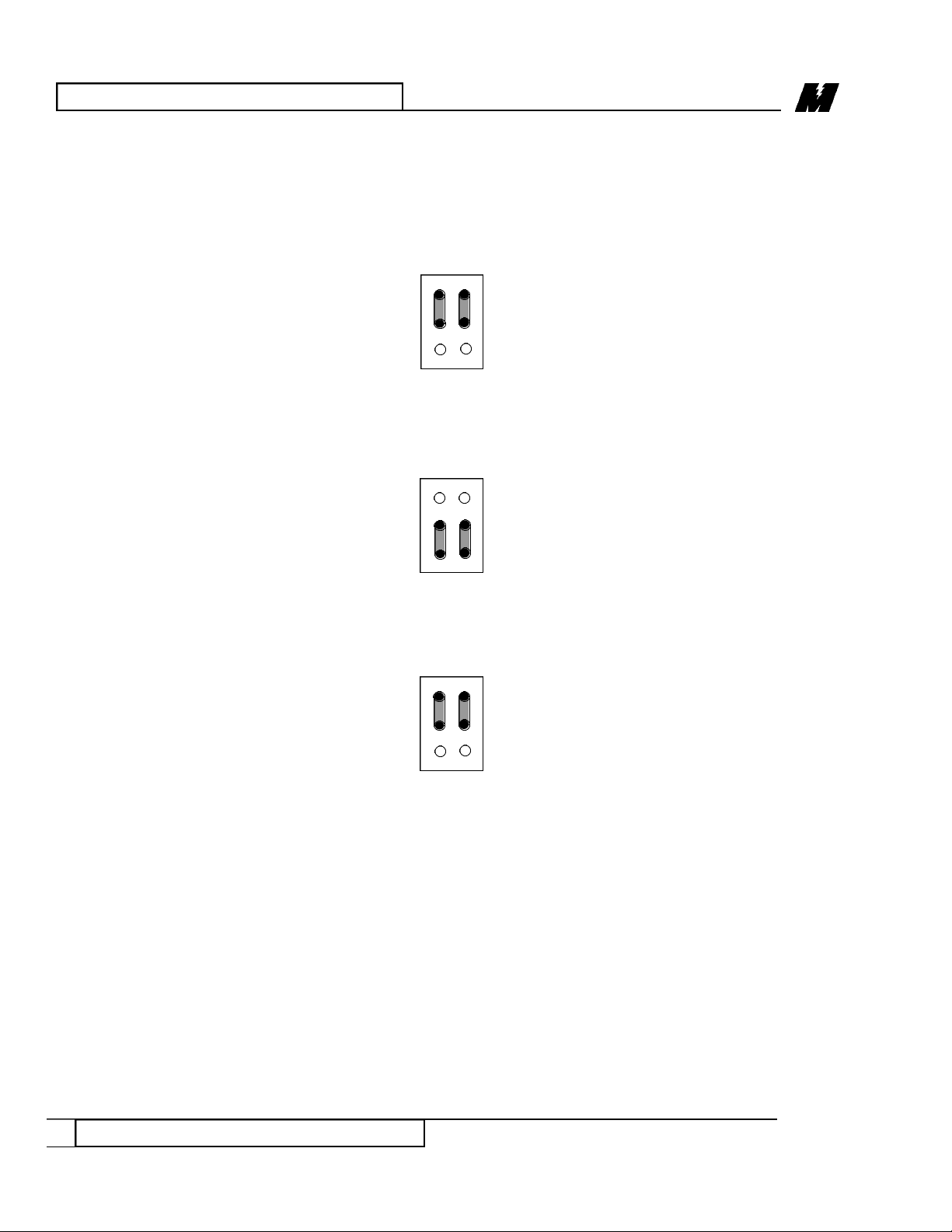
1. Position jumpers of E4 in one of the Active Hubs as shown:
This will be the master Active Hub.
2. Position jumpers of E4 in the other Active Hubs as shown:
These will be the slave Active Hubs.
3. Position jumpers of E8 in both master and slaves as shown:
These jumpers MUST be in this position in order to direct control signals
to J1. This connector distributes the timing and signals between the Hub
cards.
E4
M
S
E8
CON
BUS
E4
M
S
RD 90-279 © 1997 MagneTek, Inc. 97-04
Table des matières
Autres manuels Magnetek Changer


