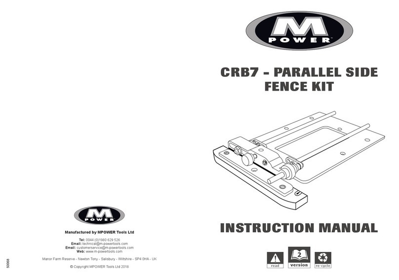
M-Power CRB7 Manuel utilisateur

CRB7- COMBINATION
ROUTER BASE MK3
INSTRUCTION
MANUAL
re-cycleread version
5

2
CRB7 - COMBINATION ROUTER
BASE MK3
Thank you for purchasing the MPOWER
Combination Router Base (CRB7), we hope you
enjoy using it.
The CRB7 should give lasting performance if
used in accordance with these instructions.
SAFETY
Please read and understand the safety points at
the end of these instructions as well as the
power tool instructions before use.
Users must be competent in safe routing
practices before using this product.
FEATURES
• Adjustable Dadoing with a Clamp Guide
• Adjustable Mortising for material
2” (50mm) > 5/16” (125mm)
• Adjustable Anti-tilt support
• Adjustable Groove Copier
• Offset Baseplate
• Small Circle Router Compass:
Min. Radius 3/4” (19mm) >8.13/16”(224mm)
• Large Circle Router Compass
Min. Radius 7” (180mm) > 25” (635mm)
Note: All dimensions shown are based on a
medium sized router being used with a 1/4”
(6.3mm) router cutter.
ITEMS REQUIRED
• Router with a suitable rod size and centers.
• Router cutter / Router bit.
• Clamps.
• 2 x 1/2” (13mm) A/F open ended spanner.
• 5/16” (8mm) A/F open ended spanner.
• Hand Tools.
CONTENTS
3. Items Enclosed
4. Setting Up
Fitting the CRB7 to your router
7. The self adhesive rule
The micro adjuster
The lock bars
8. Operation
Adjustable Dadoing with a Clamp Guide
Adjustable Mortising
Anti-tilt Support
10. Adjustable Groove Copier
Offset Baseplate
11. Cutting Small Circles
Pivot Pin Storage
12. Cutting Large Circles
13. CRB7 Accessories
Maintenance
Environmental Protection
Guarantee
14. Safety Points
The following symbols are used throughout
these instructions.
Denotes risk of personal injury, loss
of life or damage to the tool in case
of non-observance of the
instructions.
Refer to the instruction manual
provided with your power tool.

1
5
4
1D
6E
3
4B
5B
5D 5E
6
6B
6D 6F
1B
1C
2 2B
16 4 3 27 1 2 3 4 5 6 7
123 1 2 3
cm
Inches
5
11
1 Bridge
1B Bridge Spacer
1C Bridge Slot
1D Bridge pinch bolt hole
2 Baseplate
2B Baseplate Letterbox
3 Bridge Pinchbolt
4 Micro Adjuster
4B Micro Adjuster Lock Nut
5 Adjuster Guide Rod 5/16” (8mm)
5B Adjuster Guide Rod M5 Locknut
5D Adjuster Rod
5E Adjuster Rod Crank Plate
6 Fixed Guide Rod 5/16” (8mm)
6B Fixed Guide Rod M5 Locknut
3
ITEMS ENCLOSED
6D Fixed Rod
6E Fixed Rod M8 Locknut x 2
6F Fixed Rod Crank Plate
7 Offset Handle
8 Anti-tilt Leg
9 Pivot Pin
10 Mortise Pillars
11 Self adhesive Rule
12 No.6 x 1/2” Woodscrews x 6
13 M4 x 25/64’ (10mm) Screws x 3
14 9/32” (7mm) Guide Rods
15 Compass Pivot Hub
16 25/64” (10mm) Compass Rods x 2
17 No.6 x 1/2” Woodscrews x 3
18 Lock Bars X 2
(not to scale)
7
8
10
13
13
9
12
Accessories
15
18
16
14
X 6
17
X3

4
FITTING THE CRB7 TO YOUR ROUTER
1. Guide Rod selection
5
6
6E
4B
3. Initial alignment
Aligned
5
Router base
wing bolt
A
SETTING UP
Letterbox
The CRB7 is fitted with 5/16” (8mm) diameter
guide rods (5 & 6).
If the router base rod drillings are smaller, fit
the 9/32” (7mm) guide rods.
2. Loosen the Lock Nuts
Using 1 x 1/2” (13mm) spanner, slightly loosen
fixed rod nut (6E) and micro adjuster nut (4B).
Position the router in front of the CRB7.
Align the router base rod drilling (A) with
Adjuster Rod (5).
IMPORTANT
IT IS NOT ESSENTIAL TO CENTER THE
ROUTER CUTTER PRECISELY WITHIN
THE CRB7’S LETTERBOX FOR ANY
OPERATION.

5. Guide Rod adjustment4. Cutter alignment
Router
cutter
Letterbox
Router cutter
path
* 1/4”
Clearance *
X
X5
5E2
6E2
5B
5
5E1
5E2
Check that the router cutter will safely align
within the letterbox cross hatch area.
IF IT WILL, GO TO STEP 7.
IF IT WILL NOT, GO TO STEP 5.
Loosen the M5 nut (5B) using a 5/16” spanner.
Move the adjuster rod (5) to the other crank
plate drilling (5E2).
Replace washers and nuts and tighten.
For further adjustment fit the rods in the other
crank plate drillings (5E2 & 6E2).
Flip cranked adjuster rod (5) to its outer
position.
6. Crank Plate adjustment
5

7. Fitting the router 8. Setting the Fixed Rod
Aligned
6
Bridge
B
A
6E
B
Hold Still
Align fixed rod (6) with the router base rod
drilling (B), so that both rods are aligned.
Slide the router onto both rods until it stops at
the Bridge end of the CRB7 assembly.
Using 2 x 1/2” (13mm) open ended spanners,
tighten both fixed rod nuts.
Tip: Using two spanners when tightening the
fixed rod nuts will prevent the rod setting being
disturbed.
Both guide rod positions are now set.
Important - Before attempting any
machining pass:
Ensure that the router is securely fitted to the
CRB7 by checking ALL CRB7 fixings, including
router base wing bolts and micro adjuster lock
nut.
IMPORTANT
Follow the below steps in order:
1. Tighten router base wing bolt (A).
2. Finger-tighten fixed rod nut (6E).
3. Tighten router base wing bolt (B).
6

Tip: Positioning the router base Wing Bolts
towards the bridge end of the CRB7 will increase
micro adjuster accuracy.
Using the index markings
The micro adjuster and bridge have
corresponding red index lines. (1A & 4A)
1 x Micro adjuster rotation = 5/100” (1.25mm).
4 x Rotations = 3/16” (5mm).
Removing the slack from the adjuster
thread.
• Loosen both router base wing bolts and turn
the adjuster (4) in the desired direction to
engage the thread.
• Rotate until index markings (1A & 4A) align.
• Re-tighten the wing bolt on the adjuster guide
rod.
• Should the router cutter need to be adjusted
in the opposite direction repeat the above
step.
Once happy with the rule location:
• Ensure that the baseplate (2) is clean.
• Peel off the self adhesive backing paper.
• Stick in position.
THE LOCK BARS
Use the lock bars (18) to help tighten and
loosed the guide rods.
THE SELF ADHESIVE RULE
11A
16 4327 1234567
123 1 2 3
cm
Inches
5
11
11A2
4
THE MICRO ADJUSTER
• Plunge the router cutter to a level just above
the workpiece and lock in position.
• Loosen the router base wing bolt (I6) on the
fixed guide rod (6).
• Lock the router base wing bolt (I5) on the
adjuster guide rod (5).
• Rotate the micro adjuster (4) to move the
router and cutter into position.
• Lock the adjustment in position by tightening
the adjuster nut (4B) against the bridge (1).
4B
Many routers are manufactured with a cast
index line (11A).
• If the router has no index line, draw one
on the base using a fine tip marker pen.
7
18
With the router fitted to the CRB7:
• Position the rule (11) along the edge of the
router base.
A measurement can then be taken as the router
is moved.
16 4327 1234567
123 1 2 3
cm
Inches
5
61 I6
I5
4
1A 1A
5
4A

• Fit the cutter to the router and re-fit the
router onto the CRB7.
• Position the CRB7 with a mortise pillar (10)
either side of the work piece.
• Rotate the CRB7 clockwise until both mortise
pillars contact the sides of the workpiece.
• Adjust the cutter position to the mortise
markings, use the micro adjuster if required.
• Lock the router position on both guides rods
using the router wing bolts.
For a deep rebate, several light cutting
passes may be preferred.
Before use, check that the router is firmly
secured to the CRB.
Adjustable Mortising
Material widths between:
2” (50mm) > 4. 7/8” (125mm)
Fit the mortise pillars through hole locations F
Material widths between:
4 7/8” (125mm) - 8 5/8” (219mm)
Fit the mortise pillars through holes C-D or C-H
OPERATION
Adjustable Dadoing with a Clamp
Guide
• Fix the clamp guide (J) on the workpiece.
• Butt the bridge end of the CRB7 up against
the clamp guide.
• Slide the router along the guide rods to
position the cutter.
• Use the micro adjuster (4) if required.
• Lock the router position on both guides rods
using the router wing bolts (I)
Workpiece
I
J
J
4
2
Workpiece
10
2
10
C
H
2
D
F
F
Workpiece
10
10
K
C
l
o
c
k
w
i
s
e
F
• Fit the mortise pillars (10) to the underside
of the baseplate (2).
8

• Slide the anti-tilt leg (8) into the bridge
from the underside.
• Tighten the bridge pinch bolt (3) to lock it in
position.
• Slide the router onto the CRB7 rods and lock
in position using the wing bolts (I)
• Rest the CRB7 and router on the work piece
(M), then release the bridge pinchbolt (3) to
set the anti-tilt Leg depth.
• Lock the anti-tilt Leg in position.
Before routing, check that the bench
surrounding the work piece is smooth, even
and clear of obstacles.
Anti-Tilt Support
The Anti tilt leg is a two part assembly.
Max. Support height = 3 1/8” (80mm)
Min. support height = 5/16” (8mm)
If the mortise is positioned at the end of
the work piece, clamp extended battens (L)
to either side.
L
Workpiece
L
L
L
K
10
10
Workpiece
4
C
l
o
c
k
w
i
s
e
Check that the mortise pillars can complete
the mortise without running off the end of
the battens.
For a deep mortise, several light cutting
passes may be preferred.
9
8
3
8
3M
I
When cutting the mortise, ensure an even
pressure is maintained between the
mortise pillars and workpiece.

To avoid splitting the batten, pilot drill and
screw into position by hand.
• Fit the CRB7 to the router.
• Check that the batten (N) slides into the
first groove and moves smoothly along its
length.
• Set the required distance between the router
cutter and batten.
• Use the micro adjuster (4) to finely adjust cutter
position if required.
• Lock the router in position using the router base
wing bolts (I)
The second groove can now be routed.
• Slot the batten into the second groove to rout
the 3rd groove.
Adjustable Groove Copier
N
2
5
4
1
Workpiece
K
Workpiece
C
E
E
• Make copy batten (N) Min. Length 6. 5/16”
(160mm) in timber or solid plastic i.e. nylon or
polyethylene.
Note: The batten profile should copy the size and
shape of the router cutter.
• Test the batten in a sample groove to ensure a
good but not over-tight fit.
• Rout the first groove into the workpiece. Use a
clamp guide or side fence.
• Using 3 x No.6 woodscrews (12) fix the batten to
the underside of the baseplate via hole E & C.
10
• Slide the router onto the CRB7 guide rods.
• Position the router at the opposite end from
the Bridge (1).
• Lock the router in position using the wing
bolts (I)
The router cutter should just sit safely
within the baseplate ‘letterbox’.
• Fit the offset handle (7) into the bridge and
lock in position using the bridge pinchbolt (3).
Ensure that the CRB7 handle end remains
over the work piece.
7
3
I
2
1
Workpiece K
Apply
Pressure
Offset Baseplate
12
N
I
Autres manuels pour CRB7
3
Table des matières
Autres manuels M-Power Outils électriques