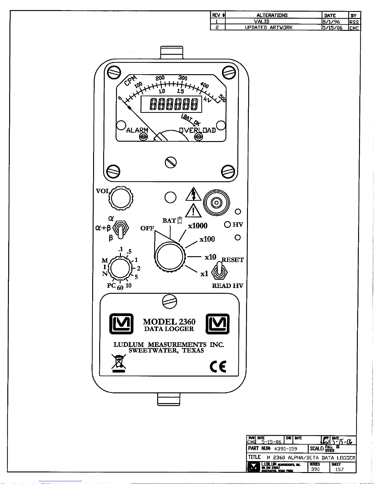
LUDLUM 2360 Manuel utilisateur

LUDLUM MODEL 2360
SCALER/RATEMETER DATA LOGGER
July 2016
Serial Number 133669 and Succeeding
Serial Numbers

LUDLUM MODEL 2360
SCALER/RATEMETER DATA LOGGER
July 2016
Serial Number 133669 and Succeeding
Serial Numbers

STATEMENT OF WARRANTY
Ludlum Measurements, Inc. warrants the products covered in this manual to be free of
defects due to workmanship, material, and design for a period of twelve months from the
date of delivery. The calibration of a product is warranted to be within its specified
accuracy limits at the time of shipment. In the event of instrument failure, notify Ludlum
Measurements to determine if repair, recalibration, or replacement is required.
This warranty excludes the replacement of photomultiplier tubes, G-M and proportional
tubes, and scintillation crystals which are broken due to excessive physical abuse or used
for purposes other than intended.
There are no warranties, express or implied, including without limitation any implied
warranty of merchantability or fitness, which extend beyond the description of the face
there of. If the product does not perform as warranted herein, purchaser’s sole remedy
shall be repair or replacement, at the option of Ludlum Measurements. In no event will
Ludlum Measurements be liable for damages, lost revenue, lost wages, or any other
incidental or consequential damages, arising from the purchase, use, or inability to use
product.
RETURN OF GOODS TO MANUFACTURER
If equipment needs to be returned to Ludlum Measurements, Inc. for repair or calibration, please send to
the address below. All shipments should include documentation containing return shipping address,
customer name, telephone number, description of service requested, and all other necessary information.
Your cooperation will expedite the return of your equipment.
LUDLUM MEASUREMENTS, INC.
ATTN: REPAIR DEPARTMENT
501 OAK STREET
SWEETWATER, TX 79556
800-622-0828 325-235-5494
FAX 325-235-4672


Ludlum Measurements, Inc. July 2016
Table of Contents
Introduction 1
Getting Started 2
Unpacking and Repacking 2-1
Battery Installation 2-1
Connecting a Detector to the Instrument 2-2
Internal Switches 2-2
Battery Test 2-2
Operating the Instrument 2-3
Principle of Operation 2-3
Specifications 3
Description of Controls and Functions 4
Operator Controls 4-1
Internal Controls 4-3
Safety Considerations 5
Environmental Conditions for Normal Use 5-1
Cleaning Instructions and Precautions 5-1
Warning Markings and Symbols 5-1
Calibration and Maintenance 6
Calibration 6-1
Establishing an Operating Point 6-1
Meter Calibration 6-2
Detector Overload Calibration 6-3
Maintenance 6-4
Recalibration 6-4
Batteries 6-5
RS-232 Interface 7
Communicating With the Model 2360 7-1
Commands 7-1
Read Commands 7-1

Model2360 TechnicalManual
Ludlum Measurements, Inc. July 2016
Set Commands 7-2
Command Descriptions 7-2
Model 2360 Interface Software 7-6
Functions 7-7
Main Screen 7-8
Auto Dump Data (Setup) 7-9
Model 2360 Interface Software Sample Printouts 7-10
Installation of the 2360 Interface Software 7-12
Removal of the Model 2360 Interface Software 7-13
Connecting to a Computer 7-13
Software License Agreement 7-14
Technical Theory of Operation 8
Amplifier/Power Supply Board 8-1
Processor Board 8-3
Troubleshooting 9
Troubleshooting Electronics that Utilize Proportional & Scintillator Type Detectors 9-1
Recycling 10
Parts List 11
Model 2360 Scaler/Ratemeter 11-1
Amplifier/Power Supply Board, Drawing 390 × 180 11-1
Processor Board, Drawing 390 × 173 11-4
LCD Display Board, Drawing 390 × 372 11-6
Calibration Board, Drawing 390 × 176 11-6
BCD Board, Drawing 261 × 107 11-6
Wiring Diagram, Drawing 390 × 179 11-7
Drawings and Diagrams 12

Model2360 TechnicalManual Section1
Ludlum Measurements, Inc. Page 1-1 July 2016
Introduction
he Ludlum Model 2360 Scaler/Ratemeter Data Logger is an easy-
to-use survey instrument incorporating the best of the analog and
digital worlds. Able to measure both alpha and beta radiation levels
simultaneously, the Model 2360 presents the data in scaler (digital
display) mode or ratemeter (analog meter) mode. The Model 2360 also logs
up to 550 data points, consisting of sample number, date/time stamp,
sample measurements (both alpha and beta, cpm if ratemeter measurement,
or counts per count time if logging scaler count), scaler count time, “S” or
“R,” identifying whether scaler count or ratemeter was logged, and location
identifier (10 characters).
Each alpha-beta data point is logged by simply pressing the button located in
the instrument handle. The appropriate scaler or ratemeter measurement is
taken, and both alpha and beta readings are logged into non-volatile
memory. An internal dipswitch allows for logging of the scaler reading,
ratemeter reading, both scaler and ratemeter readings, and NO logging. The
location identifier can be input by a PC or other RS-232 device prior to
logging a sample.
There are also 6 lines (15 characters each) of header information that can be
stored at the beginning of the non-volatile memory. The header lines can
contain such information as the user name, survey name, serial numbers, etc.
The “CALIBRATION DUE DATE” can also be stored in non-volatile memory,
which will disable the instrument when the internal clock date reaches the
stored date.
The Model 2360 has a long arc length (6.0 cm {2.4 in.}) meter face that
normally reads from 0 to 500 cpm. The main rotary switch allows for
multiplication ranges of ×1, ×10, ×100, and ×1000. The Model 2360 has a
three-position toggle switch on the front panel to switch between displaying
alpha, beta, or alpha + beta levels.
Sectio
n
1
T

Model2360 Technical Manual Section 1
Ludlum Measurements, Inc. Page 1-2 July 2016
Alpha and beta pulses have different audio tones, so that the user can
discriminate between the two. A two-position momentary action switch
allows either a meter reset, or displays the detector HV onto the meter. The
following six alarms may be set via the RS-232 port:
Alpha Ratemeter (0-999999 cpm)
Beta Ratemeter (0-999999 cpm)
Alpha + Beta Ratemeter (0-999999 cpm)
Alpha Scaler (0-999999)
Beta Scaler (0-999999)
Alpha + Beta Scaler (0-999999)
These alarm points, when exceeded, light the meter face LED, marked
ALARM, and activate the audio speaker. The ratemeter alarms are non-
latching (will cease when the radiation level drops below the alarm point).
The scaler alarm will continue until the RESET is pressed, or the next scaler
count is started.
The digital display is a full 6-digit liquid crystal display (LCD) display, which
is direct-driven for good viewing and a wide temperature response from -4
to 60 °C (40 to 140 oF). The digital display displays the scaler count, and
prior to each sample logging, displays the current sample number. The
display also has an arrow symbol for counting overflow and two colons that
indicate that a scaler count is in progress.
The Model 2360 communicates through an RS-232 port located on the
instrument can. The computer interface software is supplied on CD and
includes the following functions:
downloading of header and logged data into an ASCII file
setting and reading of instrument parameters/header
information
setting of the ˝CALIBRATION DUE DATE˝
setting of the internal real-time clock/calendar
setting of the user-definable scaler time
setting of location code and alarm points
clearing of logged memory

Model2360 Technical Manual Section 2
Ludlum Measurements, Inc. Page 2-1 July 2016
Getting Started
Unpacking and Repacking
Remove the calibration certificate and place it in a secure location. Remove
the instrument and accessories (batteries, cable, etc.) and ensure that all of
the items listed on the packing list are in the carton. Check individual item
serial numbers and ensure calibration certificates match. The Model 2360
serial number is located on the front panel below the battery compartment.
Most Ludlum Measurements, Inc. detectors have a label on the base or body
of the detector for model and serial number identification.
Important!
If multiple shipments are received, ensure that the detectors
and instruments are not interchanged. Each instrument is
calibrated to specific detectors, and is therefore not
interchangeable.
To return an instrument for repair or calibration, provide sufficient packing
material to prevent damage during shipment. Also provide appropriate
warning labels to ensure careful handling
Every returned instrument must be accompanied by an Instrument Return
Form, which can be downloaded from the Ludlum website at
www.ludlums.com. Find the form by clicking the “Support” tab and
selecting “Repair and Calibration” from the drop-down menu. Then choose
the appropriate Repair and Calibration division where you will find a link to
the form.
Battery Installation
Ensure the Model 2360 range selector switch is in the ˝OFF˝position. Open
the battery lid by pushing down and turning the quarter-turn thumbscrew
Sectio
n
2

Model2360 Technical Manual Section 2
Ludlum Measurements, Inc. Page 2-2 July 2016
counterclockwise a quarter of a turn. Install two ˝D˝size batteries in the
compartment.
Note the (+) and (-) marks inside the battery door. Match the battery
polarity to these marks. Close the battery box lid, push down, and turn the
quarter-turn thumb screw clockwise a quarter of a turn.
Note:
The center post of a flashlight battery is positive. The batteries
are placed in the battery compartment in opposite directions.
Connecting a Detector to the Instrument
Caution!
The detector operating voltage (HV) is supplied to the detector
via the detector input connector. A mild electric shock may
occur if you make contact with the center pin of the input
connector. Switch the Model 2360 to the ˝OFF˝position before
connecting or disconnecting the cable or detector.
Connect one end of a detector cable to the detector by firmly pushing the
connectors together while twisting clockwise ¼ turn. Repeat the process in
the same manner with the other end of the cable and the instrument.
Internal Switches
Release the can latches and remove the cover from the 2360, taking care not
to damage the speaker wires. Using a ball-point pen, set the switches for the
desired AUDIO division and TONE described on Page 4-3. Replace the cover
and fasten the latches.
Battery Test
The batteries should be checked each time the instrument is turned on.
Move the range selector switch to the BAT position. Ensure that the meter
needle deflects to the battery check portion on the meter scale. If the meter
does not respond, check to see if the batteries have been correctly installed.
Replace the batteries if necessary.
Table des matières