LUCIFER SSL1 Manuel utilisateur

PATHLIGHT
LED LUMINAIRE SSL1, ISL1, ISL2 & BOLLARDS
Luminaires require factory-supplied
24-Volt DC power supply, specied
separately. Integral and remote
mounted power supply options
available. Secondary run lengths
dependant of selected power supply.
Fixtures supplied with 6” lead of 18
gauge wire.
This product must be installed in
accordance with applicable electrical
and installation codes by a person
familiar with the construction and
operation of the product and the
hazards involved. “CAUTION– RISK OF
FIRE”
INSTALLATION
Before beginning any pathlight
installation, disconnect electrical power
at main switch or circuit breaker.
To reduce the risk of re, electric shock,
and potential damage to recessed
housing assembly when electrical power
is re-connected, DO NOT ATTEMPT TO
CONNECT the following on branch circuit
serving pathlight assembly:
CAUTION
•Motors •Power tools •Extension cords
•Appliances or similar electronics
A.
Fixtures to be mounted in conditions where
ambient temperatures do not exceed 40°C.
Ensure AC input voltage is protected against
surges & load shifts prior to power supply
input.
SAFETY INSTRUCTIONSB.
Read installation instructions
completely before attempting
installation.
Failure to follow instructions may
result in improper installation and
void warranty.
Contact Lucifer Lighting Company
with any questions or concerns
before beginning any installation.
Ensure qualied electrician will
perform all electrical procedures.
Disconnect electrical power
circuit before attempting to install
pathlight or power supply.
1
Pathlights are Class II LED luminaires
for discreet path lighting for
residential, commercial and hospitality
applications. Durable precision milled
316 stainless steel or brass casting.
C.
E.
DESCRIPTION
POWER
Optimum 18” (457mm) above walking
surface; 36” (915mm) on-center
spacing for SSL1 & ISL1; 60” (1524mm)
on-center spacing for ISL2 .
D. RECOMMENDED SPACING
1.
2.
3.
4.
5.

F. POWER SUPPLIES
Class 2 remote power supplies accommodate varying quantities of xtures. Power
supply must be located in a readily accessible location for future servicing.
1. REMOTE POWER SUPPLIES
REMOTE POWER SUPPLY OPTIONS
PART # Part ID
PSA-24V-60-XAT2 A
PSA-24V-XX-XXXX B
UBB-JCT-24V-60-XAT2-XXX C
A
Class
2 power supply
dimmable via 0-10V analog, reverse phase or forward phase.
Domestic version features 1/2” knockouts.
Class
2 power supply
and multiple driver options. Domestic version features 1/2”
knockouts.
Universal back box with 1/2” knockouts
, wet and concrete pour rated.
Dimmable via
0-10V analog, reverse phase or forward phase. Can be mounted using specied hanger
bars or brackets. Available for domestic and international.
B
C
3.00”(76mm)
10.5”(267mm)
4.00”(101mm)
4.700
119.37
4.700
119.38
4.70”
(119mm) 4.70”
(119mm)
2.30”(58mm)
10.5”
(227mm)
2.00”(51mm)
5.38”
(137mm)
2
1.50”
(38mm)
4.80”
(122mm)
0.80”(20mm)
1.60”
(41mm)
8.30”
(210mm)
1.30”(34mm)
Domestic International
Domestic International
When specied with integral power supply, universal back box or Bollard feature
mounting for 1 xture. Universal back box power supply can support multiple
xtures. Separate mounting components required for each xtures.
2. INTEGRAL POWER SUPPLY
3
2.9”(74mm)
luminaire
centerline

Specied collar
length
G. LUMINAIRE MOUNTING OPTIONS
SSL-UMP: Compatible with two-gang switch box or 4-square junction box for Dry
/ Damp locations and weatherproof single or two gang box for Wet and concrete
pour locations. Must use provided gasket in Wet locations.
SSL-MP-(Collar Length): For use with single gang weatherproof box for Wet and
concrete pour locations. Must use provided gasket in Wet locations.
1. MOUNTING PLATES - DRY / DAMP, WET AND CONCRETE POUR LOCATIONS
0.63”(16mm)
SSL-UMP
SSL-MP-(Collar Length)
Secure mounting
plate to customer
furnished back box
Collar to nish
ush with nished
substrate
Specied collar
length
SSL-BB
0.63”
(16mm)
SSL-BB: Includes back box, gasket and SSL-UMP mounting plate; features 1/2”
knockouts on top, bottom and back of box.
SSL-BB-(Collar Length): Includes back box, gasket and mounting plate with
specied collar length; features 1/2” knockouts on top, bottom and back of box.
Note: All unused knockout must be sealed with supplied plugs.
2. BACK BOXES - DRY / DAMP, WET AND CONCRETE POUR LOCATIONS
Collar to nish
ush with nished
substrate
SSL-BB-(Collar Length)
4
Ensure mounting component and wiring is in place before installing substrate.
Minimal tolerances exist between xture and mounting component, cutout
dimensions are critical. Part numbers & Images depicted through this guide are
applicable of SSL1 & ISL1.
SSL1 & ISL1: 2.40” (62mm)
square cutout
ISL2: 2.40” (62mm) H X
4.10” (104mm) W cutout
SSL1 & ISL1: 2.40” (62mm)
square cutout
ISL2: 2.40” (62mm) H X
4.10” (104mm) W cutout
Gasket
Gasket

1.00”
(25mm)
SSL-RM: Remodel collar for installing xture into drywall / plasterboard.
SSL-CC: Cavity collar for installing xture into cavity or bore.
SSL-SC3: Stud-mount collar, adjusts from 1/2” to 3”. Features 1/2” knockouts.
SSL-SC6: Stud-mount collar, adjusts from 3” to 6”. Features 1/2” knockouts.
3. MOUNTING COLLARS - DRY / DAMP LOCATIONS ONLY
SSL-RM
SSL-CC
0.69”(18mm)
SSL-SC3
SSL-SC6
Insert collar into cutout ush with
nished substrate; fold tabs over
to secure
Insert collar into cutout ush
with nished substrate; secure
with customer furnished screws
or nails or suitable bonding
adhesive.
2.40” (62mm)
square cutout
Extend collar
to be ush
with nished
substrate
Secure collar to
stud with customer
furnished screws
SSL1 & ISL1: 2.40” (62mm)
square cutout
ISL2: 2.40” (62mm) H X
4.10” (104mm) W cutout
SSL1 & ISL1: 2.40” (62mm)
square cutout
ISL2: 2.40” (62mm) H X
4.10” (104mm) W cutout
5

6
SSL-SMB-(Finish): Provides ush mount of luminaire. Receives secondary wiring
through back of box only.
4. SURFACE MOUNT BOX - DRY / DAMP AND WET LOCATIONS
SSL-SMB-(Finish) Mount to nished surface through back
of box with customer furnished screws
2.45”
(62mm)
3.00”
(76mm)
10.5”
(267mm) 4.00”
(101mm)
10.5”
(267mm) 4.00”
(101mm)
Can be specied with integral or remote power supply, supplied with hanger bars
or brackets, specied on order. SSL1 & ISL1 mount horizontally or vertically, ISL2
mounts horizontally only. SSL1 & ISL1: 2.40” (62mm) square cutout. ISL2: 2.40” (62mm) H
X 4.10” (104mm) W cutout.
5. UNIVERSAL BACK BOX - WET AND CONCRETE POUR LOCATIONS
1.00”(25mm)
Hanger bars adjust from 14”
(356mm) to 24” (610mm) and may
be cut to accommodate narrow stud
spacing
Brackets, universal stainless
steel mounting ange
1.00”(25mm)
Collar to nish ush with
nished substrate.
Collar
Collar
Collar to nish ush with
nished substrate

7
BOLT-DOWN
0.88”(22mm)
KOs for wiring
Base is bolted directly to mounting
surface with customer-furnished
hardware
Four 0.28”(7mm)
bolt holes
Secure bollard to base
with supplied screws
CONCRETE POUR
0.88”(22mm)
KOs for wiring
Zinc-plate J-bolts for concrete
pour mounting
Concrete Pour
Secure bollard to base
with supplied screws
4.00”
(102mm)
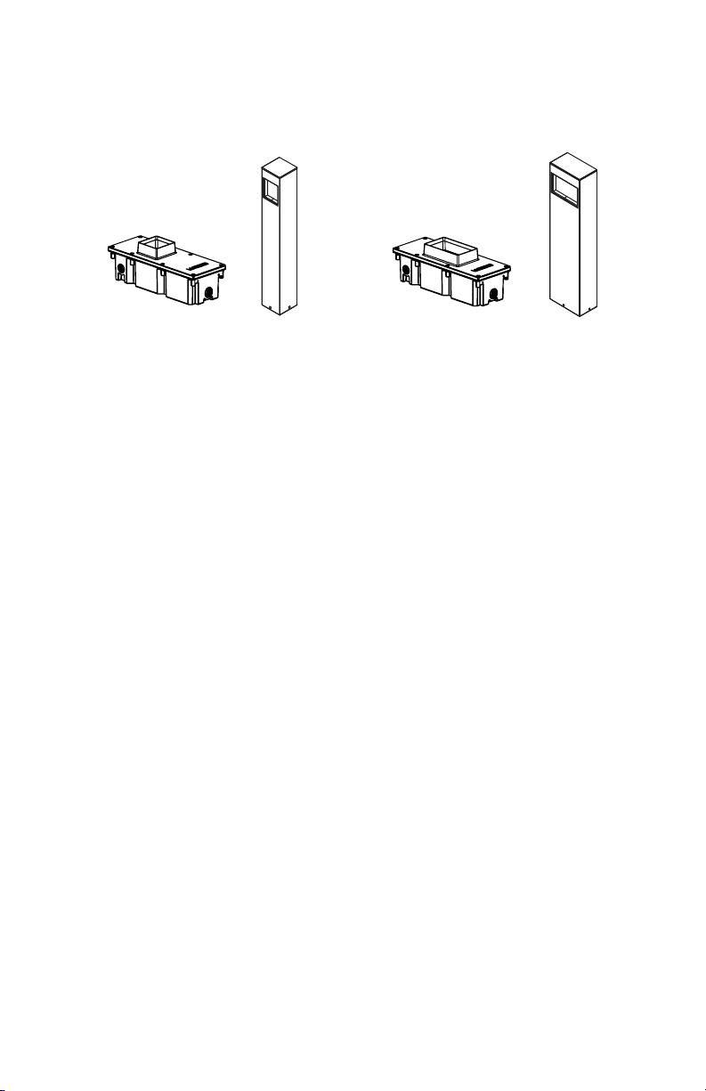
Freestanding mount, receives luminaire for ush installation, available with
integral or remote power supply. Mounting option specied on order. Ensure all
wiring is installed prior to bollard installation.
6. BOLLARD - DRY / DAMP AND WET LOCATIONS
STAKE DOWN
0.88”(22mm)
KOs for wiring
Secure bollard to base
and insert into ground
14.0”
(356mm)

H. WIRING
Access wiring compartment by removing lid and lid retaining screws. Insert line,
load and control voltage wires with appropriate conduit or strain relief ttings
through knockouts.
Connect primary and control wiring to power supply. Run secondary low voltage
wiring to each xture location in either home run or parallel method.
Home Run
Parallel
Back boxes used as example of mounting location
At each mounting location, connect low voltage wiring to factory supplied 6” lead
wire with connector for attaching to xture. See next section for mounting options.
Factory supplied
lead wires
Low voltage
wiring
8
Note: Max run distance for each secondary low
voltage wiring circuit is 40 feet.
Note: Max run distance for entire secondary low
voltage wiring circuit is 40 feet.

9
I. LUMINAIRE INSTALLATION
Place self-adhesive gasket on back of luminaire for wet locations. Connect pin
connector of pathlight to lead wire connector supplied by factory (see wiring on
page 8).
Note: Gasket not used on Bollard or Surface Mount Box
Push wires into cavity / junction box and insert xture as shown below, applying
even pressure to face of xture.
Note: If mounting device collar is not ush with substrate, springs may not fully
engage.
Fixtures designated as Locking (Wet location) feature two discreet factory supplied
locking screws. While xture is pressed in place, tighten hex screws with provided
hex key.
Spring
Gasket
(Adhesive Side)

J. SERVICING LED
If Locking (Wet location) version, loosen 2 screws located inside xture aperture
using hex key. Pull xture outward from mounting surface. A small depression is
provided on the lower backside of the tting face to aid in leveraging the xture if
necessary. Disconnect pin connector and remove gasket.
Gasket
Remove 3 hex screws and separate LED assembly from xture. Replace with OEM
LED assembly sourced through Lucifer Lighting. Ensure O-ring seats properly and
screws are tightened. Replace gasket, connect pin connector and push xture into
mounting location. If Locking (Wet location), tighten 2 screws located inside xture
aperture.
Gasket
Depression
10
O-Ring
Ce manuel convient aux modèles suivants
2
Table des matières


