Serial Controller
Section 1: Safety.............................................................................................................................5
Section 2: Quick Start................................................................................................................... 6
Step 1: Assemble Bracketry.................................................................................................7
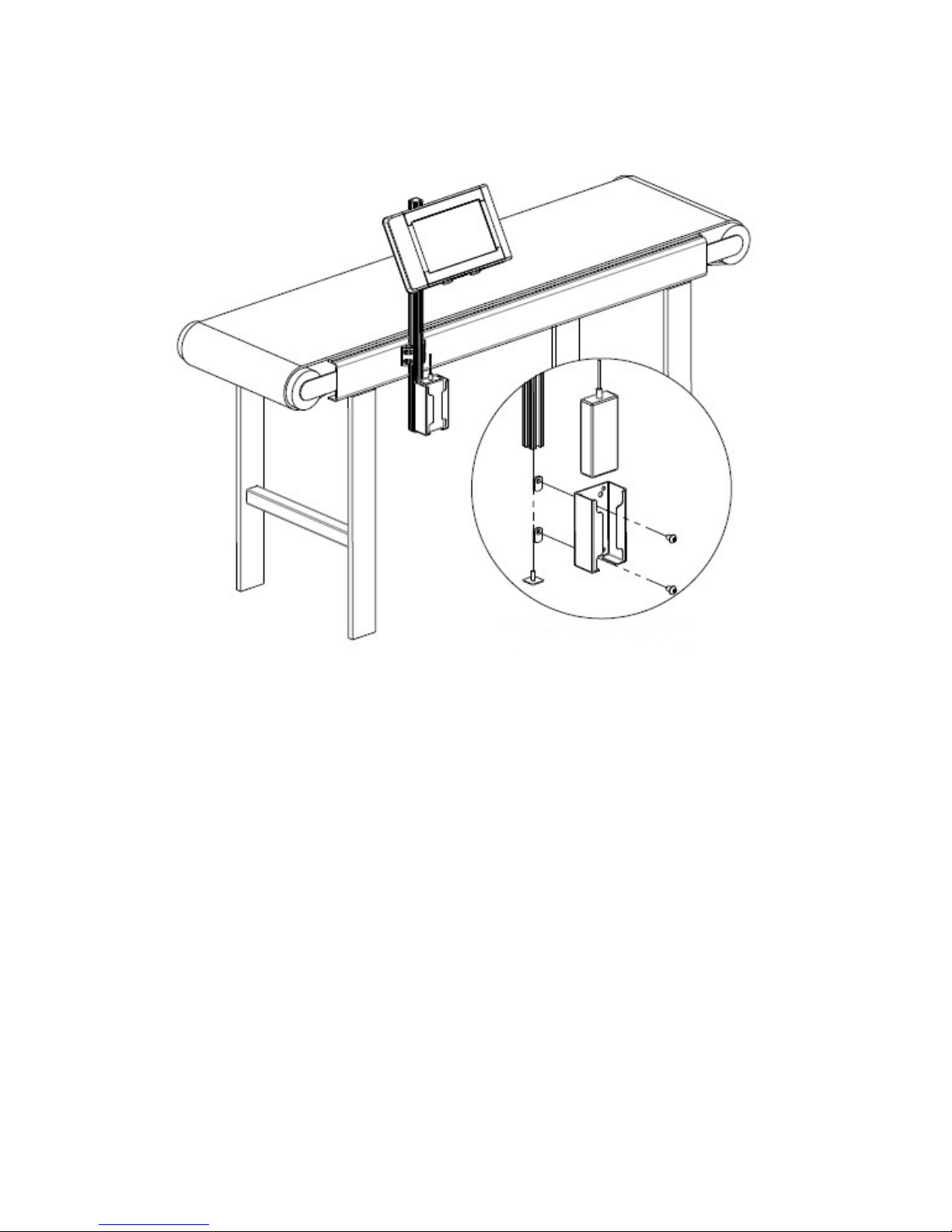
Step 2: Assemble Bracketry to Conveyor............................................................................8
Step 3: Connect controller to Print Head.............................................................................9
Step 4: Setup Print Head Via Controller............................................................................11
Step 5: Creating a Message................................................................................................16
Step 6: Print a Message......................................................................................................18
Section 3: Controller Functions..................................................................................................19
Home Screen..................................................................................................................... 19
Message Editor.................................................................................................................. 21
Time, Date, and Count Codes............................................................................................22
User Defined Time Codes..................................................................................................23
User Defined Date Codes...................................................................................................24
Product Counts, Variable Fields, Logos............................................................................25
Barcodes, Product setup, & Menu .....................................................................................26
Message Info Box............................................................................................................. 27
The Apps Screen............................................................................................................... 28
Appendix A: Specifications........................................................................................................ 30
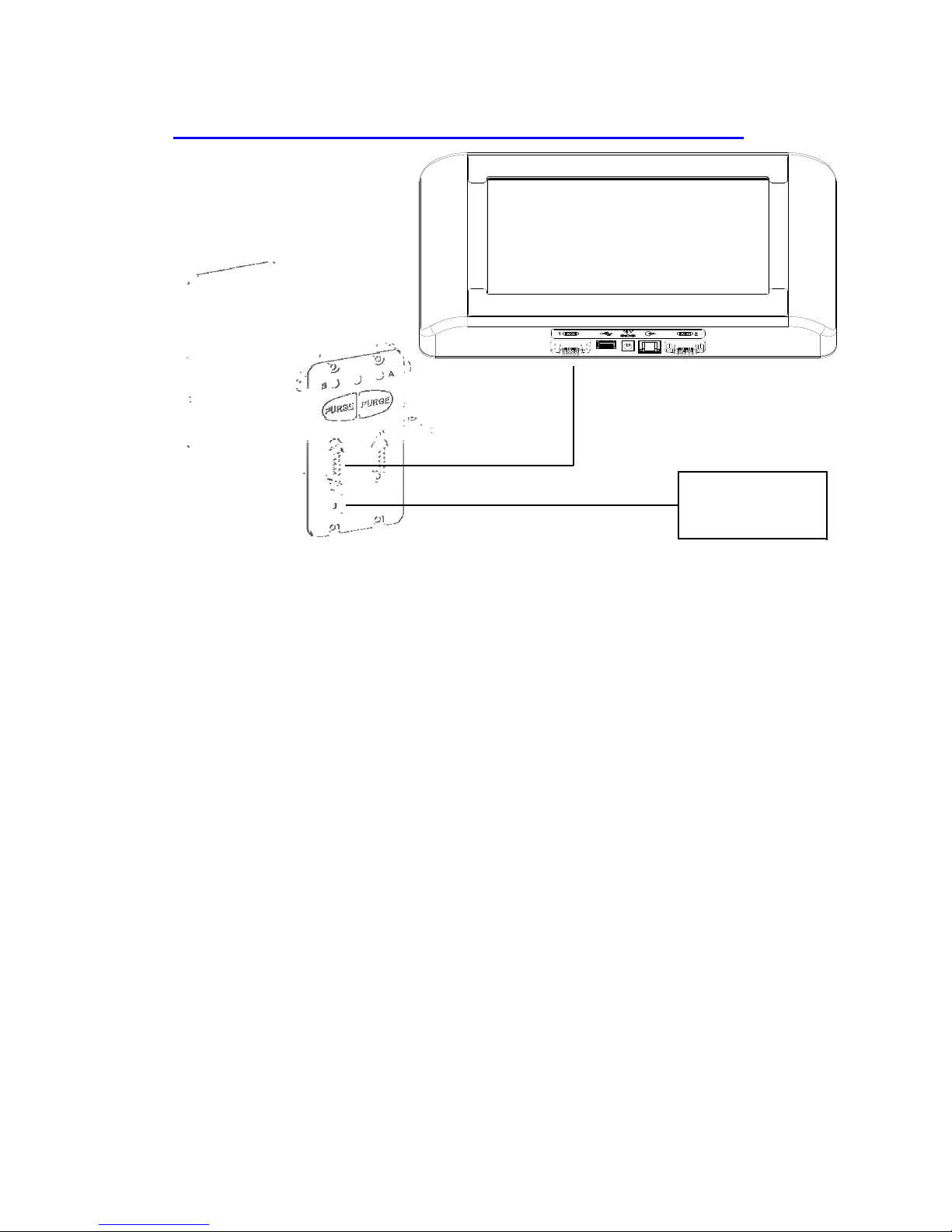
Stainless Steel Serial Controller.........................................................................................30
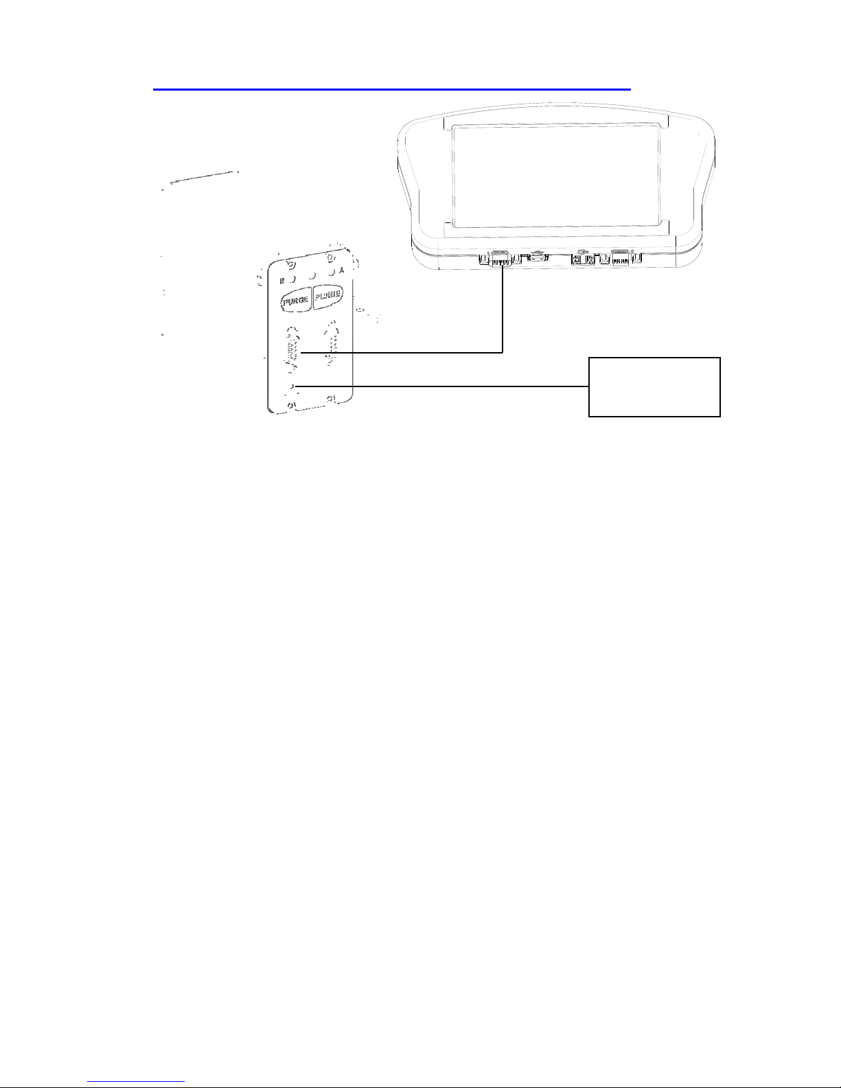
Handheld Serial Controller................................................................................................31
System Interconnect Diagram............................................................................................32
Appendix B: File System Backup and Restore..........................................................................33
Backup ...............................................................................................................................33
Restore ...............................................................................................................................33
Appendix C: Configuring a PC to Serial Controller................................................................34
Appendix D: Creating Logo Files.............................................................................................. 35
Appendix E: Controller and Print Head File Management.....................................................36
File Manager..................................................................................................................... 36
Transferring Logo and Font Files......................................................................................37
Appendix F: Part Numbers........................................................................................................ 38
System................................................................................................................................38
Service Parts...................................................................................................................... 38
Replacement Kits.............................................................................................................. 39
Optional Equipment...........................................................................................................40
Serial Controller Operations Manual Rev A 4