Locus Energy LGate 120 Manuel utilisateur

LGate 120
Installaon
Guide
Version 2.1

2
Table of Contents
Important Product Information 3
The LGate 120 Datalogger 4
Revenue-Grade Monitoring 5
Verifying Installation 7
Accessing Data on the Device 9
Inverter Direct Monitoring 12
SMA Sunny Boy 13
Power-One Aurora 15
Kaco Blueplanet 02xi 18
Fronius IG Plus 20
Emerson SPV 23
Eaton ISG PV 26
Additional Device Monitoring 28
Eaton Pow-R EVSE 28
LGate 120 FAQ 31

3
Important Product Information
DANGER – ELECTRICAL SHOCK HAZARD
!All installation and servicing on the LGate 120 and accompanying products should only
be performed by qualied personnel and only within the scope of these installation
instructions.
!Disconnect the LGate 120 from the power source (both the breaker to the LGate and
the AC disconnect) when servicing the product.
!The LGate is not intended for use in life-support applications.
Important Warranty Information
Removing or disassembling any part of the LGate 120.
The LGate 120 is backed by the Locus Energy, LLC Hardware Limited Warranty.
The following actions will void the warranty:
To obtain a copy of the Locus Energy, LLC Hardware Product Limited Warranty, please
have your head oce or program administrator contact your Locus Energy Account
Manager.
Breaking the tamper seal on the LGate 120.
Joining the RS485 or Ethernet cables to another conductor inside the meter socket.
Installing or operating the LGate 120 in any way not specied by this installation guide.
Laptop
Power drill
Wire stripper
Mounting screws
Form 2S 200A meter socket
Volt meter
Ammeter / clamp meter
Shielded twisted pair wire (for inverter
direct monitoring only)
Gel-lled crimps (for inverter direct
monitoring only)
Junction box (for inverter direct
monitoring only)
Network cable crimper
RJ45 heads (for Ethernet connection
only)
CAT5 tester (for Ethernet connection
only)
Additional CAT5 cable (for Ethernet
connection only)
Recommended Installation Tool-kit for the LGate 120

4
The LGate 120 Datalogger
RS485 / Modbus Wires
(as shipped)
RS485 /
Modbus Wires
Ethernet
Port
MAC ID
LCD
Screen

5
LGate 120
Revenue-Grade Monitoring
This section covers the installation of the LGate 120 revenue-grade core monitoring system.
This type of monitoring works with single-phase inverters and power sources up to 200A.
IMPORTANT: The LGate 120 does not ship with a meter socket included. For proper
installation, the LGate 120 meter must be mounted in an installer-supplied meter socket
that meets the following specications:
Form Factor 2S
Current rating of 200A or higher
Voltage rating of 600VAC or higher
All-weather rating (for outdoor installations)
!
Note: Conrm the installation has been performed correctly and to code before leaving the site.
1. Mounting the LGate Socket
Mount the meter socket (purchased separately) between the PV system and the electrical
panel. Run the AC lines from the combined inverter output through the meter socket -
line side to load side - and to the PV breaker on the electrical panel, then attach the
LGate 120 meter to the meter socket.
Ground the meter socket to the ground in the main panel.
L1 L2 G
N
L1
PV
Breaker
Utility PV System
Line Side
RS485 / Modbus
Connection
L1
L2
Form 2S 200A 600V MB
All Weather Enclosure
Ethernet
Connection
Main
Panel
L2
Note: If using a solar-dedicated subpanel, label the panel with “PV Loads Only” signage.
Note: If this installation does not require inverter direct monitoring, the RS485 / Modbus
Connection wires should be stored inside the meter base with the heat shrink cap left on.
Note: When installing the meter in the meter base and securing the meter base cover, avoid
pinching the RS485 / Modbus Connection and Ethernet Connection wires.
Load Side

6
2. Connecting to the Internet
The LGate 120 requires a network connection to communicate. The cell modem is the
primary method of communication; if there is no cellular reception or using the cell
modem is not an option, then use the secondary method, installing an Ethernet cable.
Note: Store the unused Ethernet cable inside the meter box with the coupler left on.
Note: Run the Ethernet cable in a separate conduit from power conductors, at least 1’ away.
Note: The LGate can hold up to 1.5-2 months of data without an internet connection. Please
ensure that the unit does not lose an internet connection for longer than 1.5 months to ensure
that no data is lost.
Preferred Connection Method - Cell Modem
The LGate 120 comes installed with a cell modem. No additional conguration is
necessary for this method.
Secondary Connection Method - Ethernet Cable
Connect the LGate to a DHCP router with a CAT5 Ethernet cable, as shown below.
Make sure this connection is continuous (i.e. the router is not regularly turned o).
LGate 120
L1 L2 GN
L1
PV
Breaker
Utility PV System
Main
Panel
L2
LAN
Connection
DHCP Network
Router or Switch
Max. patch cable
length: 300’
Note: If using the Ethernet connection, some additional conguration is required (see the
Enabling the Ethernet Connection section on page 10 for more information).

7
Verifying Installation
Verify proper installation of the LGate 120 using the steps below. The correct LED screen
conguration is marked with a symbol.
1. Power Connection
The LGate has initialized correctly.
The LGate doesn’t have power: Check the dedicated breaker and the
voltage at the meter socket.
The phone icon on the LED screen indicates the network connection of
the LGate 120.
2. Internet Connection
Solid phone icon: The last data packet was sent successfully.
Blinking phone icon:
1. Blinking quickly: The last data packet was not sent successfully but the cellular signal
strength (if applicable) is strong.
2. Blinking slowly: The last data packet was not sent successfully and the cellular signal
strength (if applicable) is weak.
No phone icon: The LGate 120 is not connected to the network. For an Ethernet cable
connection, double-check the pin-out on the Ethernet cable (see the FAQ section on page
31 for more information). For a cell modem connection, contact technical support to
troubleshoot.
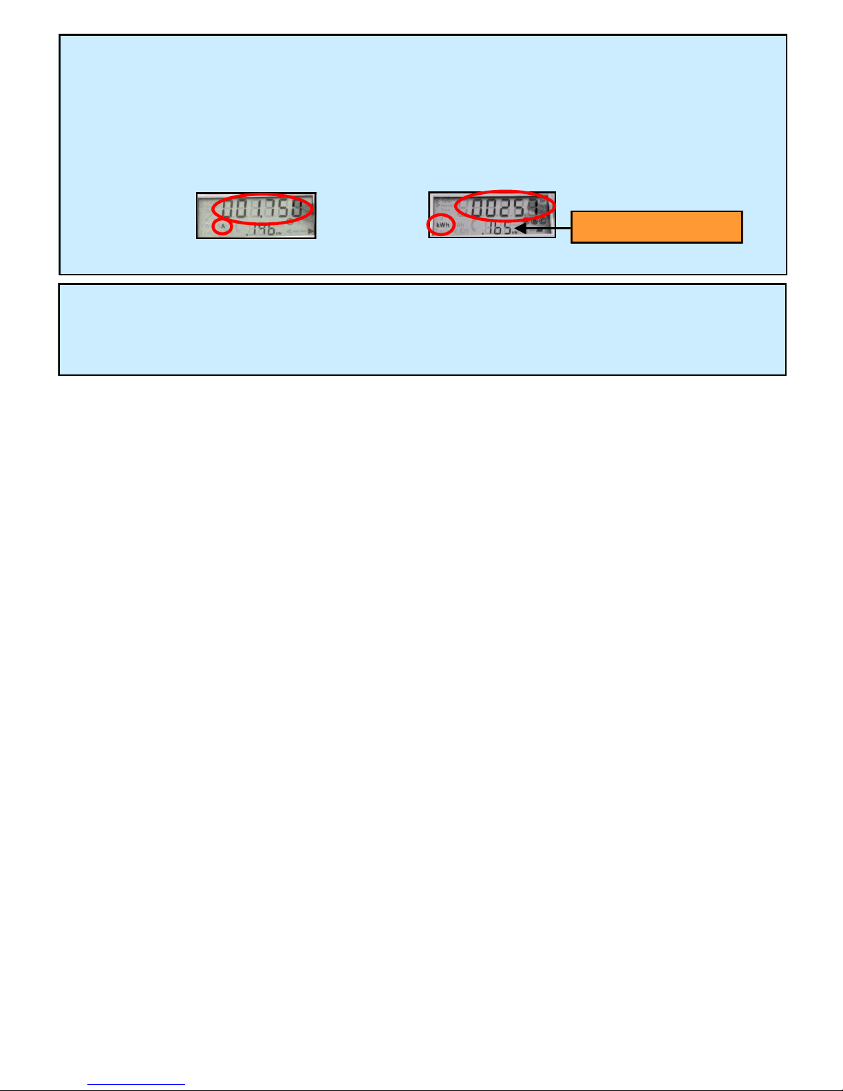
3. Meter Placement Check
The arrow on the bottom right-hand side of the LED screen
indicates the direction of energy ow through the meter
socket, depending on the direction of the arrow.
Pointing toward the right (see image at right): The meter was installed correctly.
Meter Placement Arrow
Pointing toward the left: If the PV system is on and generating energy, the meter socket
was installed backward. Verify that the inverter wires running through the meter socket
go from line side to load side (top to bottom).
4. RS485 / Modbus Connection
The switch icon indicates if any RS485 / Modbus devices are connected.
If unsure whether inverter direct monitoring has been purchased for
this project, contact your company, lease provider, or program admin.
Switch icon is on: All external devices are communicating correctly (comm 1 or 2).
Switch icon is o: At least one of the external devices is not communicating OR the LGate
is not congured for external devices. Verify that all RS485 / Modbus connections are
wired and terminated correctly and that the external devices are addressed accordingly.
8
Energy (kWh) Reading
Power (kW) Reading
Current (A) Reading
5. Reading Verication
Check that the energy (kWh), power (kW), and current (A) readings that cycle on the LED
screen match the inverter output.
If power readings are negative, the meter socket was installed backward. Verify that the
inverter wires running through the meter socket go from line side to load side (top to
bottom).
6. Installation Conrmation
Contact your oce, program administrator, or lease provider to conrm the system is
connected.

9
Accessing Data on the Device
Every LGate 120 device comes loaded with updated software, which provides:
More secure data transfer to SolarOS; and
The ability to log into the LGate with a laptop to view conguration settings.
Logging into the LGate
1. Reset the LGate 120 by turning o the AC disconnect and breaker to the LGate for 30
seconds, then back on again.
2. Connect the LGate 120 directly to a laptop using the LGate’s Ethernet cable.
3. In a web browser, enter 169.254.12.13 in the address bar and select Enter (see below).
4. Use the password networkcong and select the Login button to enter the password-
protected menu (see below).
B
A
A
B

10
Enabling the Ethernet Connection
The LGate 120 comes precongured for a cellular connection. If the cellular option is not
possible, enable the Ethernet Connection by selecting false in the Cell Mode drop-down
menu and the Save Conguration button.
Selecting true (the default value) in the Cell Mode drop-down menu enables the cellular
connection.
Navigating the Password-Protected Menu
Once logged into the LGate 120, you can view the following information:
1. Basic information about the LGate: IP address, rmware type, and MAC ID (see below)
2. All devices sending data and their instantaneous data readings (see below)
3. Network settings: cell modem status, static IP address, proxy server, and compression
conguration options (see below)
A
BC
C
B
A
Table des matières


