Little Giant OA1S Series Manuel utilisateur

OA1S Series Oil Sensing Unit
OWNER'S MANUAL
English
EN
The Oil/Water Detection control sump system is designed and approved to
safely operate pumps and monitor elevator sump pits, transformer vaults,
and leachate wells. It will activate a pump to remove water from elevator
pits in accordance with ASME A17.1 / CSA B44.
Indicator lights will illuminate on the control panel for power, pump run-
ning, high alarm, high oil, and pump overload (optional). Green LEDs indi-
cate Power and Pump Run. Red LEDs indicate alarms, activated sensors, or
system settings. The panel has a set of auxiliary contacts that activate on
power loss or high oil/water conditions. If the liquid level reaches the alarm
probe and high-level float, the system will differentiate between OA1S
water and oil and activate the remote alarm.
This product is covered by a Limited Warranty for a period of 3 years from the date of original purchase by
the consumer. For complete warranty information, refer to www.LittleGiant.com.
Specifications
Sensor
• SJEOOW (UL) / SJTOOW (CSA)
• 18 AWG, 5-conductor, flexible, and water/oil resistant
High Level Switch
• 1 foot (0.3 m) cable
• Narrow angle, normally closed
• SJOOW (UL/CSA)
• 18 AWG, 5-conductor, flexible, and water/oil resistant
Sensor Input Ratings
• Float/Function Inputs: 3.3 VDC
• Water Probe Inputs: 12 V
Model Maximum HP Volts Amps Hz Cord Length
ft (m)
OA1S120C14-L 1 115 1-14 60 25 (7.6)
OA1S230C14-L 2 230

SAFETY INSTRUCTIONS
Specifications
2
Pump Kit
SAFETY INSTRUCTIONS
This equipment should be installed and serviced by technically qualified personnel who are familiar with
the correct selection and use of appropriate tools, equipment, and procedures. Failure to comply with
national and local electrical and plumbing codes and within Little Giant recommendations may result in
electrical shock or fire hazard, unsatisfactory performance, or equipment failure.
Know the product’s application, limitations, and potential hazards. Read and follow instructions carefully to
avoid injury and property damage. Do not disassemble or repair unit unless described in this manual.
Refer to product data plate(s) for additional precautions, operating instructions and specifications.
Failure to follow installation or operation procedures and all applicable codes may result in the following
hazards:
Model HP HZ Volts Pump
Model
Pump Performance
(GPM/LPM) Shut
Off
ft (m) PSI
10 ft (3 m) 20 ft (6.1 m)
OA1S-10ECH-1 1/2 60 115 10ECH-CIM 55 (208.2) 45 (170.3) 60
(18.3) 26
Phase/Pump Type Single phase, simplex
Pump Power Receptacle Cable 120 or 240 VAC, 15 A, 60 Hz, female plug
Incoming System Power Cable 120 or 240 VAC, 15 A, 60 Hz, male plug, 6 ft (1.8 m) cable
IEC Motor Contactor (optional overload) 120 or 240 VAC, 18 A, 50/60 Hz, 3-Pole, normally open,
overload amp range
Buzzer 5-30 VDC, 95 dB @ 2 ft (0.6 m)
Test/Silence Switch Single pole, single throw
Auxiliary Dry Alarm Contacts
(control panel)
120 VAC/24 VDC, 250mA maximum (each), normally
open
Fuses Positive temperature coefficient (PTC), resettable
Enclosure Thermoplastic, 8x6x4 inches, Type 4X, indoor/outdoor,
enclosure screws
Certifications cULus 508
Risk of death, personal injury, or property damage due to explosion,
fire, or electric shock.
• Do not use to pump flammable, combustible, or explosive fluids such as gasoline, fuel oil, kerosene, etc.
• Do not use in explosive atmospheres or hazardous locations as classified by the NEC, ANSI/NFPA70.
• Do not handle a pump or pump motor with wet hands or when standing on a wet or damp surface, or in water.
• When a pump is in its application, do not touch the motor, pipes, or water until the unit is unplugged or electrically
disconnected.
• If the power disconnect is out of sight, lock it in the open position and tag it to prevent unexpected application of
power.

INSTALLATION
Typical Installation
3
INSTALLATION
Typical Installation
Risk of severe injury or death by electrical shock.
• To reduce risk of electrical shock, disconnect power before working on or around the system.
• Check local electrical and building codes before installation. The installation must be in accordance with their regu-
lations as well as the most recent National Electrical Code (NEC) and the Occupational Safety and Health Act
(OSHA).
• Wire pump system for correct voltage.
• This product is supplied with a grounding conductor and grounding-type attachment plug. To reduce risk of electric
shock, be certain that it is connected only to a properly grounded grounding-type receptacle. Do not remove the
third prong from the plug. The third prong is to ground the pump to help prevent possible electric shock hazard.
• Check electrical outlets with a circuit analyzer to ensure power, neutral, and ground wires are properly connected.
• Do not use an extension cord.
Risk of bodily injury, electric shock, or equipment damage.
• This equipment must not be used by children or persons with reduced physical, sensory or mental abilities, or lack-
ing in experience and expertise, unless supervised or instructed. Children may not use the equipment, nor may they
play with the unit or in the immediate vicinity.
• Operation of this equipment requires detailed installation and operation instructions provided in this manual. Read
entire manual before starting installation and operation. End User should receive and retain manual for future use.
1 Control panel with local alarm
2 Preset level sensor
3 Pump
4 Optional remote alarm panel
(mounted up to 2,500 feet)
5 Oil detection float
6 Alarm probe
7 Pump start probe
8 Pump stop probe
9 Pumping range, 6-inches
(15.24 cm)
1
4
2
3
5
6
7
8
9

ELECTRICAL CONNECTIONS
Physical Installation
4
Physical Installation
NOTE: No adjustment of the preset level sensor holder is required.
1. Attach the sensor holder to a discharge pipe using the stainless steel pipe clamp.
• Secure the sensor so that its stop probe reaches below the top of the pump and stops above the
pump intake level.
• Ensure the sensor is clear of inlet water and at least 2 inches away from any conductive material.
IMPORTANT: Failure to properly secure the sensor may cause the pump to activate even when oil
is present in the sump.
2. Route the preset level sensor cord to the control panel through the liquid-tight cord connector.
3. Tighten the compression nut.
4. Mount the control panel within 5 feet of an electrical outlet and 25 feet of the preset level sensor.
• Use four mounting screws.
ELECTRICAL CONNECTIONS
1. Position the preset level sensor.
IMPORTANT: If sensor cable splicing is required, use liquid-
tight junction boxes, conduit, and connectors in accordance
with national and local codes.
NOTE: Standard THHN wire, 600VAC, 18AWG is the mini-
mum wire necessary for cable splicing.
2. Review the following sections and wire for the desired applica-
tion.
System Operation
Wire an alarm security system or building automation system (BAS) to
the panel through the pump run auxiliary contacts. When the preset
level sensor activates the pump and it runs, the panel’s pump run LED
will illuminate and the auxiliary contacts will activate.
Color Terminal Block Wire Connection
Green G Pump stop probe
Yellow Y Pump start probe
Red R High water probe
White W Wire 1, oil detection float
Black B Wire 2, oil detection float
1
C1OWTC2P
Pump Run Auxiliary Inputs
BAS

ELECTRICAL CONNECTIONS
System Operation Remote Notification
5
System Operation Remote Notification
Wire the alarm auxiliary contacts of the panel directly to the alarm security system or BAS for remote
notification of system operation.
• Use 18 gauge 6-conductor wire.
• Normally open dry contacts can each switch 250mA maximum 120VAC/24VDC.
Remote Alarm Panel (Optional)
NOTE: Refer to the alarm panel manual for
complete product hazards and instructions.
Wire the remote alarm panel to the sensor
panel inputs terminals.
• The alarm panel can be mounted up
to 2500 feet from the control panel
for remote alarm notification.
Function Input (FI)
Fire Alarm Input
Wire an alarm security system or BAS to the panel. When the contacts
close, the pump will run on any liquid detection during fire alarm condition.
• If connecting the panel to an alarm security system or BAS, use 18
gauge 2-conductor wire.
Low Level / Redundant Off Alarm
Wire a normally open float switch. When the float switch deactivates and
the contacts open, the system will stop the pump and activate a low level
alarm condition.
• The P3 LED light will activate with the alarm.
• Refer to “Change Settings” on page 7 to configure.
Power Cables
1. Ensure the pump power and power outlet match the panel voltage.
2. Plug the pump power cable into the incoming pump power
cable grip on the panel.
3. Plug the incoming system power cable to a power outlet or
receptacle within 5 ft of the mounted panel.
4. Ensure the male power cord always remains at least 2 inches
from the preset level sensor cord.
• Separate these cords both in the tank and above ground.
Normally Open Dry Contacts Function
C1 and O High Oil Alarm
C1 and W High Water Alarm
C1 and T Trouble Alarm
C2 and P Pump Run Sensor
C1OWTC2P
COM CH1 CH2 CH3
Control Panel Alarm Panel
GYRWBFI
GYRWBFI
Fire Alarm Input
Low Level/Redundant O Alarm
2
3

CONFIGURATION
Remote Alarm Panel (Optional)
6
CONFIGURATION
1. Set the water sensor sensitivity potentiometer.
• Use a slotted screwdriver to rotate the sensi-
tivity adjust potentiometer on the control
panel, setting the level sensor probes to
greater or lesser sensitivities.
• Set the sensitivity adjust potentiometer to 50
kΩ during installation and only adjust if nec-
essary.
• The potentiometer sensitivity can be set from 10-100 kΩ.
2. Configure the Hand-Off-Auto (HOA) switch.
• H: Hand mode starts the pump, which will run (regardless
of sensor statuses) until the switch is toggled to O.
• O: Off mode turns the pump off (regardless of sensor sta-
tuses) until the switch is toggled to H or A.
• A: Auto mode enables the system sensors to turn the pump
on and off.
3. Turn on the pump exerciser, if desired.
• When the pump exerciser is activated, the panel will run the
pump for a 3-second interval, if the pump has been idle for
more than a week.
• The F1 LED will turn on when the exerciser is enabled.
• Refer to “Change Settings” on page 7 to configure.
Alarms
The sensor comes with two factory-enabled alarm settings:
• The level sensor error detection is triggered if the probes on the preset level sensor are activated
out of sequence. The P1 LED indicates that this setting is enabled.
• The automatic alarm reset is indicated by the P2 LED light.
• Refer to “Change Settings” on page 7 to configure.
Alarm Test
NOTE: To silence an alarm during troubleshooting, flip the test/silence switch upwards. The buzzer will
turn off while the alarm LEDs remain illuminated.
Flip the alarm test switch on the exterior left side of the panel up and hold:
• The alarm buzzer will go off.
• The top row of LEDs will light up in a solid pattern.
• The bottom row of LEDs will slowly blink in sequence.
• The buzzer and LED test pattern will stop once the switch is released.
Clearing Alarms
• Only necessary if the automatic alarm reset is disabled.
• Press and hold Test Configure for at least five seconds to clear the alarm.
• If the alarm condition is present, the alarm will reactivate.

OPERATION
View Settings
7
OPERATION
View Settings
To view the current settings of the system, press and hold Test Configure for at least 5 seconds:
• The high water, high oil, and trouble alarm will illuminate in a solid pattern.
• The P1, P2, P3, and F1 LEDs will slowly blink.
• Alarm buzzer will sound.
Change Settings
1. Press and hold Test Configure for at least 10 seconds:
• The high water, high oil, and trouble alarm LEDs will deactivate.
• Alarm buzzer will deactivate.
• P1-F1 LEDs will pulse in a rapid pattern then blinks from the left LED (P1) to the right LED (F1).
2. Release Test Configure when the desired setting’s LED blinks:
• A medium blinking pattern confirms the selected setting.
• The system displays the new system setting as a solid light, followed by a burst of fast blinking
on all LED indicators.
• The system returns to normal operation.
NOTE: To exit the “Change Settings” process without saving any selections, continue to press the Test
Configure pushbutton until the fast blinking LED pattern moves past the F1 indicator and the system
returns to the test blink pattern with the alarm buzzer sounding. Then release the pushbutton.
Operation Testing
1. Plug the pump's power cord into the control panel outlet cable.
2. Test the high-oil circuit.
• Lift the float switch with the sump empty of water.
• When the float is lifted only the High Oil indicator will be illuminated.
• The auxiliary contacts in the control panel and the remote alarm will activate.
3. Test a pump cycle.
• Make sure the discharge plumbing is directed correctly.
• Slowly fill the tank with water until the water reaches the center start probe.
• Make sure the pump turns on and operates until the water level falls below the off probe.
• Check the discharge plumbing for leaks.
4. Test the high-water circuit.
• Unplug the pump from the control panel.
• Slowly fill the tank until the water level reaches the alarm probe.
• Make sure the High Water indicator illuminates.
• Verify that the auxiliary contacts in the control panel activate the remote alarm.
5. Test the remote alarm for power loss (if installed).
• Unplug the power cord on the control panel.
• The auxiliary contacts should close and the remote alarm should activate.
6. Test the alarm panel.
• Verify the green power light is on.
• Press Alarm Test and make sure the red alarm light and buzzer turn on.
• While holding Alarm Test, press Alarm Silence. Make sure the buzzer turns off, but the alarm light
remains on.
• Release Alarm Test so the alarm light turns off and the green light turns on again.
MAINTENANCE
Periodic Maintenance
Franklin Electric Co., Inc. | Oklahoma City, OK 73157-2010
800.701.7894 |littlegiant.com
For technical assistance, parts, or repair, please contact:
10000015085 Rev. 000 06/23 Copyright © 2023, Franklin Electric, Co., Inc. All rights reserved.
7. If used, test the battery backup system.
• Unplug the wall-mounted power supply.
• Make sure the green light turns off and the pump continues running.
8. Press Alarm Test to make sure that the red alarm light and buzzer turn on.
• If the buzzer sounds quieter than with the normal power supply, replace the battery.
MAINTENANCE
Periodic Maintenance
• Clean the preset level sensor with alcohol.
• Clean the probes yearly.
• Replace the alarm panel’s 9 VDC battery yearly.
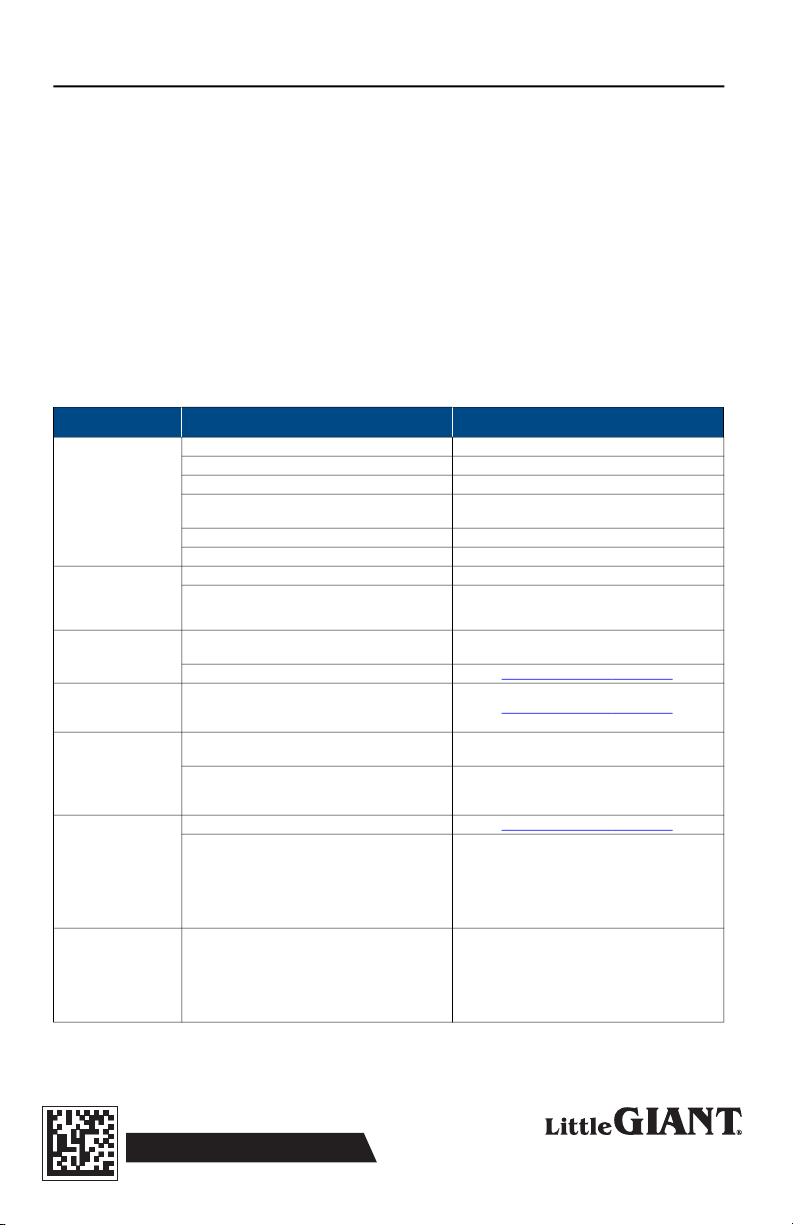
Troubleshooting
Problem Probable Causes Corrective Action
Pump does not run
Panel not plugged into outlet Plug power cord into outlet and check power.
Pump not plugged into panel Plug pump into panel plug.
Defective contactor or overload module Replace contactor or module.
Pump hand-off-auto (HOA) selector switch is in
the OFF position Toggle the pump hand-off-auto (HOA) selector
switch to either the HAND or AUTO position.
Loose level sensor wires Tighten wire connections.
Pump failure Replace pump.
Pump turns off before
the water level recedes
below the pump stop
probe (longest)
Poor pump or system ground Check grounding system and wire terminations.
Preset level sensor has dirty, corroded, or dam-
aged probes Clean or replace the reset level sensor.
Pump runs continu-
ously
Pump hand-off-auto (HOA) selector switch is in
the HAND position (manual pump operation) Toggle the pump hand-off-auto (HOA) selector
switch to either the OFF or AUTO position
Improper installation of the preset level sensor Refer to “Physical Installation” on page 4.
Level sensor error
detected (system set-
ting)
Preset level sensor incorrectly wired to the control
panel terminal connections Refer to “Physical Installation” on page 4.
Trouble alarm is acti-
vated and the over-
load relay is tripped
Check the overload module, make sure the dial is
set for the full load amps (FLA) of the pump Set the dial on the overload module to the full
load amps (FLA) of the pump
Pump is clogged or defective Clear any debris from the pump and check the
pump for normal operation, if needed replace the
pump
High oil alarm (oil
detected) activated
with no oil present in
the sump basin
Improper installation of the preset level sensor Refer to “Physical Installation” on page 4.
High level float switch has an obstruction in the
sump basin (i.e., the float or cable hung up on
another item in the basin and contacts activated)
• Clear obstruction so the high level float switch
can operate properly.
• Make sure the float and cable are free of any
other obstructions.
• The alarm condition should clear when the
float switch is deactivated.
The sensor(s) are acti-
vated, but the red
LEDs on the circuit
board are illuminated
and the buzzer is not
annunciating
The test/silence switch has been toggled to the
silence position
Deactivate or disconnect the sensor(s) and then
reactivate or reconnect the sensor(s) to ensure
normal operation resumes.

Unidad de detección de aceite de la serie OA1S
MANUAL DEL PROPIETARIO
ES
Español
El sistema de sumidero para controlar la detección de agua/aceite está
diseñado y aprobado para el funcionamiento seguro de bombas y el con-
trol de pozos de sumidero de ascensores, bóvedas de transformadores y
pozos de lixiviación. Esto hará que una bomba elimine el agua de los pozos
de ascensores conforme a la norma ASMEA17.1/CSAB44.
En el panel de control, se encenderán las luces indicadoras de alimenta-
ción, bomba en funcionamiento, alarma alta, aceite alto y sobrecarga de la
bomba (opcional). Las luces LED verdes indican que la bomba recibe ali-
mentación (Power) y está funcionando (Pump Run). Las luces LED rojas indi-
can alarmas, sensores activados o ajustes del sistema. El panel tiene un
conjunto de contactos auxiliares que se activan en caso de pérdida de
alimentación o niveles altos aceite/agua. Si el nivel de líquido alcanza la sonda de la alarma y el flotante de
nivel alto, el sistema diferenciará entre agua y aceite y activará la alarma remota.
Este producto está cubierto por una garantía limitada por un período de 3 años desde la fecha original de
compra por parte del consumidor. Para obtener información completa sobre la garantía, consulte
www.LittleGiant.com.
Especificaciones
El Sensor
• SJEOOW (UL) / SJTOOW (CSA)
• 18AWG (calibre de alambre estadounidense), 5conductores, flexible, y resistente al agua y el aceite
Interruptor de nivel alto
• Cable de 30 cm (1pulg)
• Ángulo angosto, normalmente cerrado
• SJOOW (UL/CSA)
• 18AWG (calibre de alambre estadounidense), 5conductores, flexible, y resistente al agua y el aceite
Valores de entrada del sensor
• Entradas del flotante/función: 3.3VCC
• Entradas de la sonda de agua: 12 voltios
Modelo HP Máximo Voltios Amperios Hz Longitud del cable
m (pies)
OA1S120C14-L 1 115 1-14 60 7.6 (25)
OA1S230C14-L 2 230

INSTRUCCIONES SOBRE SEGURIDAD
Especificaciones
10
Kit de bomba
INSTRUCCIONES SOBRE SEGURIDAD
La instalación y el mantenimiento de este equipo deben estar a cargo de personal con capacitación técnica
que esté familiarizado con la correcta elección y uso de las herramientas, equipos y procedimientos ade-
cuados. El hecho de no cumplir con los códigos eléctricos nacionales y locales y con las recomendaciones
de Little Giant puede provocar peligros de descarga eléctrica o incendio, desempeños insatisfactorios o
fallas del equipo.
Lea con atención y siga estas instrucciones y las que vienen con la bomba para evitar lesiones y daños a la
propiedad. Lea y siga las instrucciones cuidadosamente para evitar lesiones y daños a los bienes. No
desarme ni repare la unidad salvo que esté descrito en este manual.
Consulte las placas de datos del producto para obtener precauciones adicionales, instrucciones de funcio-
namiento y especificaciones.
El hecho de no seguir los procedimientos de instalación o funcionamiento y todos los códigos aplicables
puede ocasionar los siguientes peligros:
Modelo HP HZ Voltios Modelo de
bomba
Rendimiento de la
bomba (GPM / LPM) Apagado
m (pies) PSI
3 m
(10 pies) 6.1 m
(20 pies)
OA1S-10ECH-1 1/2 60 115 10ECH-CIM 208.2 (55) 170.3 (45) 18.3 (60) 26
Tipo de fase/bomba Monofásico, simplex
Cable del receptáculo de alimentación de la
bomba
120 o 240 VCA, 15 A, 60 Hz, enchufe hembra
Cable entrante de alimentación del sistema 120 o 240 VCA, 15 A, 60 Hz, enchufe macho, 1.8 m (6 pies)
Contactor IEC para motor (con sobrecarga
opcional)
120 or 240 VCA, 18 A, 50/60 Hz, 3patas, normalmente abierto, rango
de amperios de sobrecarga
Claxon 5-30 VCC, 95dB, @ 0.6 m (2 pies)
Interruptor de prueba/silencio Una sola pata, una sola posición activa
Contactos auxiliares de alarma por pozo seco
(panel de control)
120 VCA/24 VCC, 250mA máximo (cada uno), normalmente abierto
Fusibles Coeficiente de temperatura positivo (PTC), reajustable
Recinto Termoplástica, 8x6x4 pulg, Tipo 4X, interior/exterior, tornillos del
recinto
Certificaciones cULus 508
Riesgo de muerte, lesiones personales o daños materiales por
explosión, incendio o descarga eléctrica.
• No usar para bombear líquidos inflamables, combustibles o explosivos como gasolina, combustóleo, queroseno, etc.
• No usar en atmósferas explosivas ni lugares peligrosos según la clasificación de la NEC, ANSI/NFPA70.
• No manipule la bomba ni el motor de la bomba con las manos mojadas o parado sobre una superficie mojada o húmeda
o en agua.
• Cuando haya una bomba en su aplicación, no toque el motor, las tuberías ni el agua sino hasta haber desenchufado o
eléctricamente desconectado la unidad.
• Si la desconexión de alimentación está fuera del sitio, bloquéela en la posición abierta y etiquétela para evitar una cone-
xión inesperada de la alimentación.
Ce manuel convient aux modèles suivants
2
Table des matières
Langues :


