Lindab Plexus Guide d'installation et d'utilisation

Plexus
Service & maintenance
|py

Plexus
2
|py
We reserve the right to make changes
1.0 Installation
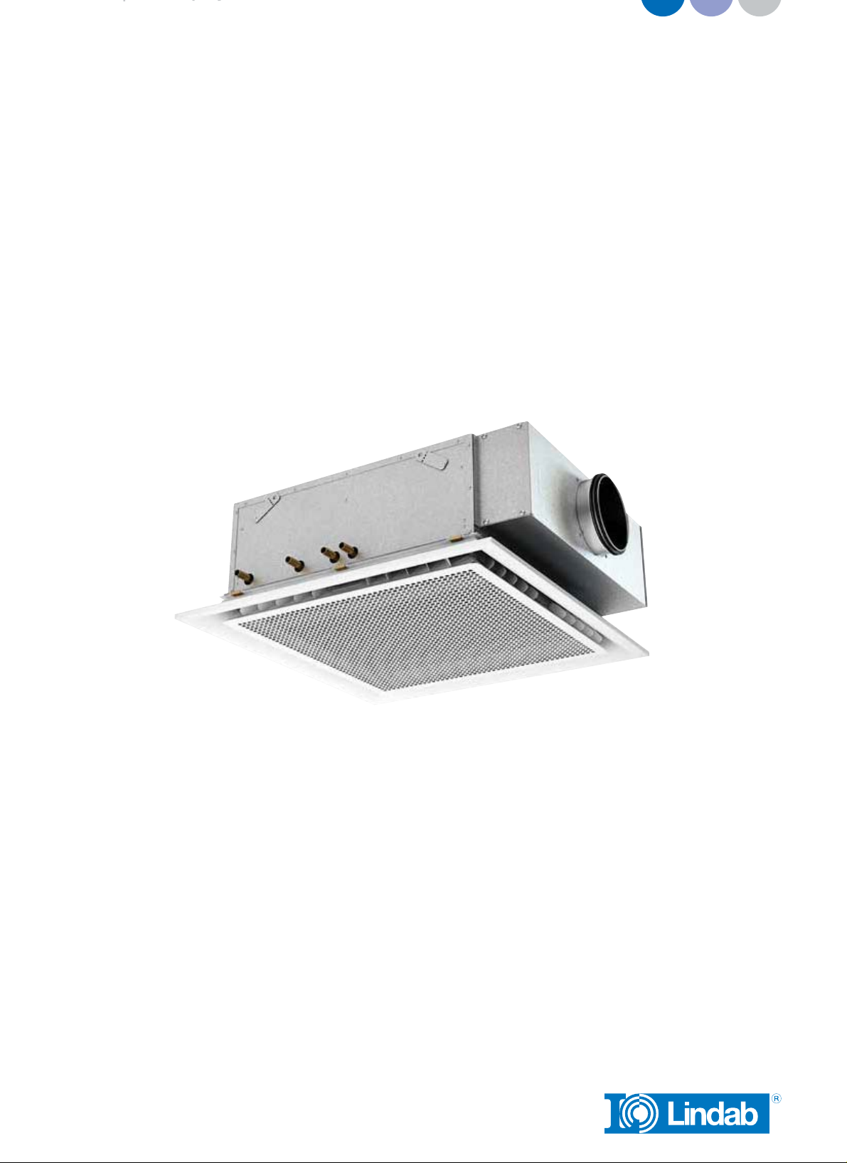
1.1 Product description
Plexus is provided with fixed lamellas which controls the primary air into non-parallel
jets in a 360 degree air pattern. The 360 degree air pattern results in shorter air
throws and a draft free indoor climate. Plexus can be used for both cooling, heating
and ventilation. The possibilities are many and the flexibility large.
1.2 Handling
The beam must be handled with care, ensuring that the beam does not sustain dents,
scratches or bends during installation.
Always seek to lift the beam at multiple points.
– Do not lift in pipes
– Do not lift in edges
– Each beam is equipped with protective film to avoid any damage during transport
and handling at building site. The film needs to be removed before commissioning
the products.
1.3 Mounting instruction
– Please visit www.lindqst.com
• Select Documentation Finder
• Select “Plexus”
• Select “Mounting”
1.4 Air connection installation
The primary air supply should be connected with instructions from a ventilation spe-
cialist. Lindab’s chilled beams can beneficially be used together with Lindab’s Safe®
duct systems.
1.5 Connection description water
Flow indication arrows are shown on the inlet and return pipes in order to assist the
installer. If the beam has been ordered with integrated valves, a special direction
of the flow must be upheld to ensure correct flow through the thermostatic valve. If
the beam has been delivered without integrated valves, the flow can be reversed,
depending on the location of the retrofitted valve. Please note the flow direction indi-
cator on the valve to insure correct installation in relation to the desired flow.

Plexus
3
|py
We reserve the right to make changes
1.5.1 Push-on fittings
– Please ensure that all pipes and fittings are undamaged, as even small dents and
scratches potentially pose a risk of leakage in the system. Always remember to do
a pressure test after assembly of the pipe work.
– Both flow and return pipe is covered by a plastic or rubber protection cover,
which should be removed before installation.
After removing the protection cover, make sure that the pipe is intact and undam-
aged, especially at the pipe end. Crocked or in other ways imperfect pipe ends will
result in leaks. Deburr the pipe on the inside and the outside, using a deburring tool
before installation
– Mount a push-on fitting to the pipe. Make sure to press the fitting all the way onto
the pipe. Consult the installation guide for the specific fitting for further details on
proper installation.
Push-on fitting

Plexus
4
|py
We reserve the right to make changes
Push-on valve
Notice! The connection pipes are internally soft-welded why it’s not allowed to
solder the beam to the pipes.
1.5.2 Compression fitting
– Please ensure that all pipes and fittings are undamaged, as even small dents and
scratches potentially pose a risk of leakage in the system. Always remember to do
a pressure test after assembly of the pipe work.
– While mounting a compression fitting, the pipe will be exposed to a big amount
of force, creating a risk of crushing the pipe. To ensure that the pipe won’t be
crushed when mounting the compression fitting, a copper insert should be
inserted into the pipe.
– Both flow and return pipe is covered by a plastic or rubber protection cover
during transport, which must be removed before installation.
– After removing the protection cover, make sure that the pipe is intact and undam-
aged, especially at the pipe end. Crocked or in other ways imperfect pipe ends
will result in leaks. Deburr the pipe on the inside and the outside, using a deburr-
ing tool before installation

Plexus
5
|py
We reserve the right to make changes
– The copper insert should be placed inside the pipe on the beam. Always support
the copper pipe coil when inserting the copper insert into position.
– Mount a compression coupling and/or a valve to the pipe. Don’t stress the nut too
much, since this may crush the pipe.
Notice! The connection pipes are internally soft-welded why it’s not allowed to solder
the beam to the pipes.
1.5.3 Flex hoses
Our flexible hoses can be used with both compression and Tectite fitting. We recom-
mend using Tectite fittings, for easier and faster mounting.
– Please ensure that all pipes and fittings are undamaged, as even small dents and
scratches potentially pose a risk of leakage in the system. Always remember to do
a pressure test after assembly of the pipe work.
– Both flow and return pipe is covered by a plastic or rubber protection cover,
which should be removed before installation.

Plexus
6
|py
We reserve the right to make changes
After removing the protection cover, make sure that the pipe is intact and undam-
aged, especially at the pipe end. Crocked or in other ways imperfect pipe ends will
result in leaks. Deburr the pipe on the inside and the outside, using a deburring tool
before installation
– Mount a push-on fitting to the pipe. Make sure to press the fitting all the way onto
the pipe. After mounting the push-on fitting, mount the flexible hose. Make sure
that the flexible hose is pushed fully into the fitting. Consult the installation guide
for the specific fitting for further details on proper installation.
Push-on fitting
Push-on valve
Notice! The connection pipes are internally soft-welded why it’s not allowed to
solder the beam to the pipes.

Plexus
7
|py
We reserve the right to make changes
2.0 Commissioning
2.1 Product labeling
Plexus I Fig.1: Label location exterior (Air connection end), Fig.2: Label location inte-
rior (On faceplate, water connection end). Plexus F Fig.1: Label location exterior (On
plastic wrapping), Fig.2: Label location interior (On faceplate, water connection end).
Plexus F Fig.1: Label location exterior (On delivery package), Fig.2: Label location
interior (Inside air outlet).
On the label you’ll find:
– Order: Order identification number.
– Pos: Order position.
– Product: Product configuration.
– Project: Project name.
– Mark: Marking noted on order.
– Nozzles: Number of nozzles.
– Plugs: Number of plugged nozzles.
– Product ID: Product number.
– Sign: To be signed when checked and commissioned on site.
2.2 Measure air pressure and calculating the airflow.
Before calculating the airflow, the static nozzle pressure must first be measured. The
static nozzle pressure is the air pressure available at the nozzles.

Plexus
8
30
40
50
60
70
80
100
120
20 30 40 50 60 70 80 100 150
0123456789
qa[l/s]
Δpt[Pa]
qa[m3/h]
4 5 6 7 8 9 10 15 20 25 30 35 40
8 9 10 11 13 15 20 25 30 35 40 50 60 70
30
40
50
60
70
80
100
120
30 40 50 60 70 80 100 150 200 250
0123456789
Δpt[Pa]
qa[l/s]
qa[m3/h]
0123456789
30
40
50
60
70
80
100
120
20 30 40 50 60 70 80 100 150
4 5 6 7 8 9 10 15 20 25 30 35 40
qa[l/s]
qa[m3/h]
Δpt[Pa]
|py
We reserve the right to make changes
2.2.1 Measure the static nozzle pressure.
– To measure the air pressure, a manometer, analog or digital (such as the Lindab
PC410) will be needed.
– Insert the measuring tube onto the specialized measuring nozzle
– Read off the static nozzle pressure from the manometer
2.2.2 Calculating the airflow
– After measuring the static nozzle pressure, read the setting of the four pins in the
corners to find the mean value of the pins.
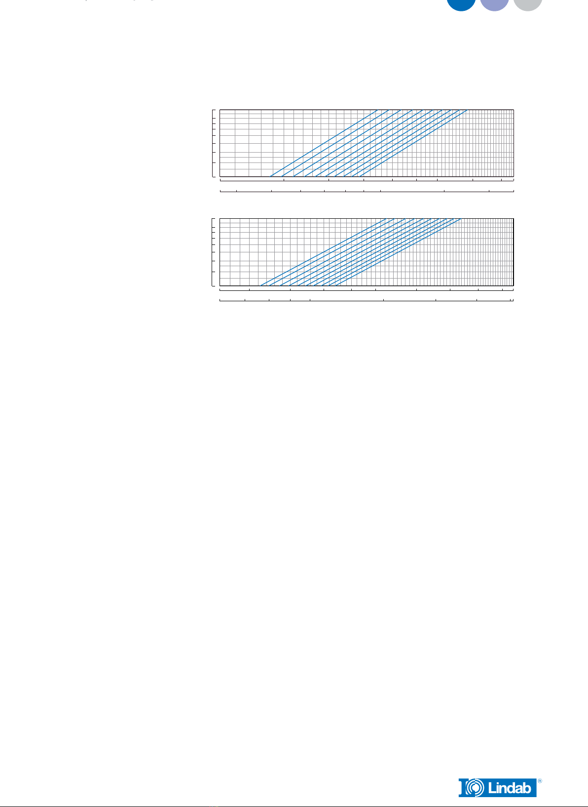
– Locate the diagram on the faceplate or see diagram 1, and use the static nozzle
pressure and the mean value of the pins to find the current airflow.
Plexus L60 Position of JetCone adjustment pins
Plexus S120 Position of JetCone adjustment pins
Plexus S60 Position of JetCone adjustment pins

Plexus
9
qa[l/s]
qa[m3/h]
10 15 20 25 30 35 40 50 60
40 50 60 70 80 100 150 200
30
40
50
60
70
80
100
120 01 23456789
Δpt[Pa]
20 25 30 35 40 50 60 70 80
30
40
50
60
70
80
100
120
70 80 90 100 150 200 250 300
01 2 34 56789
qa[l/s]
qa[m3/h]
Δpt[Pa]
|py
We reserve the right to make changes
2.3 Changing the airflow
– Measure the static nozzle pressure
– Locate the air pressure/airflow diagram on the faceplate, or see diagram 1.
– Find the mean value of the four pins to reach the desired airflow, in the diagram
on the faceplate. Use the static nozzle pressure and the desired airflow to find the
mean value of the four pins.
– Adjust the four pins in the corners, so the mean value of the pins will correspond
with the mean value found in the diagram.
– Example: Pin setting: 6+6+8+8 = 28 / 4 = mean value 7.
Plexus M60 Position of JetCone adjustment pins
Plexus H60 Position of JetCone adjustment pins

Plexus
10
|py
We reserve the right to make changes
3.0 Maintenance
3.0 Maintenance
The interval of cleaning depends on the indoor environment where the beam is
placed. Under optimal conditions the Plexus beams only need cleaning every 5 years.
3.1 Cleaning instructions
– Remove the faceplate
– Clean underneath the battery with a vacuum cleaner and a piece of wet cloth
– Only use lukewarm water and a mild detergent.
3.2 Models with down fold battery
– Remove the faceplate
– Unscrew the four screws on the battery, as described in the mounting instruc-
tion. Note that the two screws closest to the battery connection pipes must not
be completely unscrewed. Refer to the mounting instruction for details on this
matter.
– It is now possible to fold the battery down.
Autres manuels pour Plexus
1
Table des matières
Autres manuels Lindab Unité de traitement de l'air