Lasermet ICS-KP14 Manuel utilisateur

ICS-KP14 Instruction Manual
01850-53-000 Issue 3 19 January 2021
LASERMET
ICS-KP14
INSTRUCTION MANUAL
ACCESS KEYPAD WITH
DUAL CHANNEL OVERRIDE TIMER

ICS-KP14 Instruction Manual
01850-53-000 Page 2 of 18 Issue 3 19 January 2021
LASERMET ICS-KP14
Instruction Manual
Contents
1 Declaration of Conformity .................................................................................................. 3
2 Safety Warnings .................................................................................................................. 4
3 Concept ............................................................................................................................... 5
3.1 Configuration Options ................................................................................................. 5
4 Installation .......................................................................................................................... 6
5 Wiring ................................................................................................................................. 8
5.1 Connecting to Lasermet ICS Control Panels ................................................................ 9
5.2 Internal Door Release ................................................................................................ 10
5.3 Connecting to Door Lock ........................................................................................... 11
5.4 Connecting two or more Keypads to one ICS ........................................................... 11
6 Fixing ................................................................................................................................. 12
6.1 Attaching the Keypad to the Backplate..................................................................... 12
6.2 Removing the Keypad from the Wall ........................................................................ 12
7 Programming .................................................................................................................... 13
8 LED Indicators ................................................................................................................... 15
9 Operation .......................................................................................................................... 16
9.1 Default Settings ......................................................................................................... 16
10 Specifications ................................................................................................................ 17
11 Warranty ....................................................................................................................... 17
12 Contact Details .............................................................................................................. 18

ICS-KP14 Instruction Manual
01850-53-000 Page 3 of 18 Issue 3 19 January 2021
1 Declaration of Conformity
LASERMET LIMITED
ICS-KP14 Keypad
Drawing Number 01850-00-000
DECLARATION OF CONFORMITY
This is to certify that the ICS-KP14 Access Keypad with Override designated by Lasermet
Drawing Number 01850-00-000 has been tested in accordance with the following
directives and standards and found to comply.
Lasermet certifies that this product complies with the basic requirements for health and
safety as provided by the following directives and standards:
Directives: Low Voltage Directive 2014/35/EU
CE Marking Directive 93/68/EEC
EMC Directive 2014/30/EU
Standards: EN 60950-1:2006 +A2:2013
Information Technology Equipment Part 1: General Requirements
EN 61000 tbc
Electromagnetic Compatibility
Supplier:
Lasermet Limited
Lasermet House
137 Hankinson Road
Bournemouth
BH9 1HR
Dorset
United Kingdom
Country of Origin: England
Date: 3 November 2019

ICS-KP14 Instruction Manual
01850-53-000 Page 4 of 18 Issue 3 19 January 2021
2 Safety Warnings
This device is intended to be used as part of a safety system which may be used to protect personnel
and equipment from possible injury, damage, or loss.
As such it must be installed and wired according to these instructions and tested by suitably qualified
persons. No attempt may be made to tamper with the parts, open them, or use them outside of the
parameters contained herein.
The units are only designed to be fixed to surfaces using their inbuilt fixing holes. They must not come
into contact with each other or any other moving part when in use. The parts should never be subject
to impact or mechanical strain.
Safety switches should never be defeated or bypassed. It is imperative that all steps are taken to
ensure that any spare actuators are made unavailable, such that they cannot be used to defeat the
switch or reduce the protection offered by the system in any way.

ICS-KP14 Instruction Manual
01850-53-000 Page 5 of 18 Issue 3 19 January 2021
3 Concept
The ICS-KP14 Keypad is intended to be used in conjunction with Lasermet’s Laser Interlock systems
for the purpose of inhibiting access to a hazardous area to unauthorised persons. Normally this means
persons without the necessary training and personal protective equipment for the area concerned.
The keypad is sited outside a door which is electrically locked and monitored by the interlock system.
The keypad is not intended to be used as part of a security system.
The keypad has two timers which may be programmed to activate for a defined time interval when
the correct 4-digit user code is entered. When wired into a Lasermet interlock system, one output is
used to unlock the door and one to activate the override function to allow the door to be opened
without tripping out the laser.
The keypad may either be wired to the interlock control panel to override all the door switches, or to
the contacts of the adjacent door such that only one door is defeated. It is possible to program the
keypad to disable either of the timer outputs. This may be used for example where the door is not
fitted with an electric lock, in which case the door lock function would be disabled.
The override timer function is of a dual-channel cross-checked configuration and is designed to
achieve a safety performance level of PL ‘e’ to EN13849 when correctly wired to a suitable interlock
system.
Lasermet provides a full range of laser interlock equipment including control systems, interlock
switches, illuminated warning signs, laser shutters, door locks, external power supplies etc. which can
be connected to provide a complete laser interlock system. Full support, design and installation is
available from Lasermet, please contact us for any queries. Contact details are given at the end of this
manual.
3.1 Configuration Options
The ICS-KP14 Keypad has two outputs which activate for a set time when the correct 4-digit user code
is entered: the Override output and the Door Unlock output. Each output illuminates a corresponding
indication on the keypad when activated.
Each output may be independently programmed to activate for a set time between 1 and 30 seconds
when the correct code is entered on the keypad. An output is disabled by programming it to operate
for 0 seconds.
For laser interlock systems in which the entry door is electrically locked, e.g. by a maglock, the Door
Unlock output should be used to release the door, and the Door Unlock time should be programmed
for the required door lock release time.
If there is no electric lock on the door, the Door Unlock output is not used and the Door Unlock time
should be set to 0 to disable the indication on the keypad.

ICS-KP14 Instruction Manual
01850-53-000 Page 6 of 18 Issue 3 19 January 2021
The entry door will normally be fitted with an interlock switch that indicates to the interlock control
system that the door has been opened and this will cause the laser to be disabled. The Override output
should be used when it is desired to be able to open the entry door without disabling the laser. The
Override time should be set to the shortest reasonable time required for the door to be opened and
then closed again.
If it is desired to be able to release the door lock only i.e. the laser will be disabled by the door contact
when the door opens, the Override output can be disabled by setting the time duration to 0.
The ICS-KP14 has a remote activation input which may be wired to a separate pushbutton switch. This
is usually provided on the inside of the controlled door and allows persons to leave the controlled area
without disabling the laser. When the button is pressed, the keypad performs the same functions as
if the user code had been entered.
4 Installation
The ICS-KP14 is designed to be permanently attached to a wall or other fixed vertical surface.
The ICS-KP14 should be mounted in a convenient position for use and wiring. Normally it is located on
the outside (‘safe’) side of the entry door of the controlled area, on the wall adjacent to the door
handle, approximately 1.2m up from floor level.
During installation, wired connections will need to be made from the ICS-KP14 to the Interlock Control
System and possibly the door interlock switch and magnetic door lock, and allowance should be made
for the installation of electrical conduit or trunking if required to make entry to the unit.
Ideally the keypad should be attached directly to the wall with the cables being fed from within the
wall. For hollow walls this should be straightforward. For solid walls it may be easiest and neatest to
feed the cables right through the wall from the other side.
Alternatively, the keypad may be attached to a round conduit box which may be buried or surface-
mounted, though this last option will result in the unit projecting further from the wall, making it less
stable and more vulnerable.
It is recommended that the centre of mounting is at least 100mm horizontally from the door
surround/architrave and at least 150mm from the edge of the door. There must be a flat unobstructed
area of wall extending at least 70mm above and 110mm below the mounting centre to allow fitment
and removal.
If a Lasermet Miniature Warning Sign is being fitted above the keypad the centres should be at least
140mm apart vertically.
Refer to the diagram below for details of the fixing holes and cable entry. The rear cover is secured
using preferably four screws on a 35.4mm square around the cable entry point. The rear cover may
be used as a marking template. If using a round BESA conduit box, the holes will align with the cover
fixing holes.

ICS-KP14 Instruction Manual
01850-53-000 Page 7 of 18 Issue 3 19 January 2021
Once all the holes have been made, secure the rear cover as shown in the diagram below.
Feed the cables through the hole in the centre of the rear cover.
Make the electrical connections before attaching the unit to the rear cover, see the Wiring section.
Figure 1. Wall Drilling Details

ICS-KP14 Instruction Manual
01850-53-000 Page 8 of 18 Issue 3 19 January 2021
5 Wiring
The keypad is powered by 24VDC. A four-way plug-in terminal block J8 is provided for the control and
power connections, and it is usually easiest to unplug the terminals while making the connections.
Figure 2. Terminal Identification
The power supply is connected with the positive to the +24V terminal and the negative to the GND
terminal.
The REM input can be connected to a separate pushbutton switch to activate the keypad remotely.
When the button is pressed, the keypad activates its outputs according to the programmed settings
as though the correct code had been entered on the keypad. The pushbutton is wired between the
REM and +24V terminals. If this function is not required, simply make no connection to the REM
terminal.
The O/R terminal is the override output. The keypad connects this terminal to +24V while the override
is active.
Terminal Block J6 provides two isolated volt-free contacts which close when the override timer is
active. Terminal block J5 provides two isolated volt-free changeover contacts which operate when the
lock timer is active.

ICS-KP14 Instruction Manual
01850-53-000 Page 9 of 18 Issue 3 19 January 2021
5.1 Connecting to Lasermet ICS Control Panels
The ICS-KP14 may be connected such that it either overrides the individual door to which it is
associated (local override), or to override all doors in the system (global override).
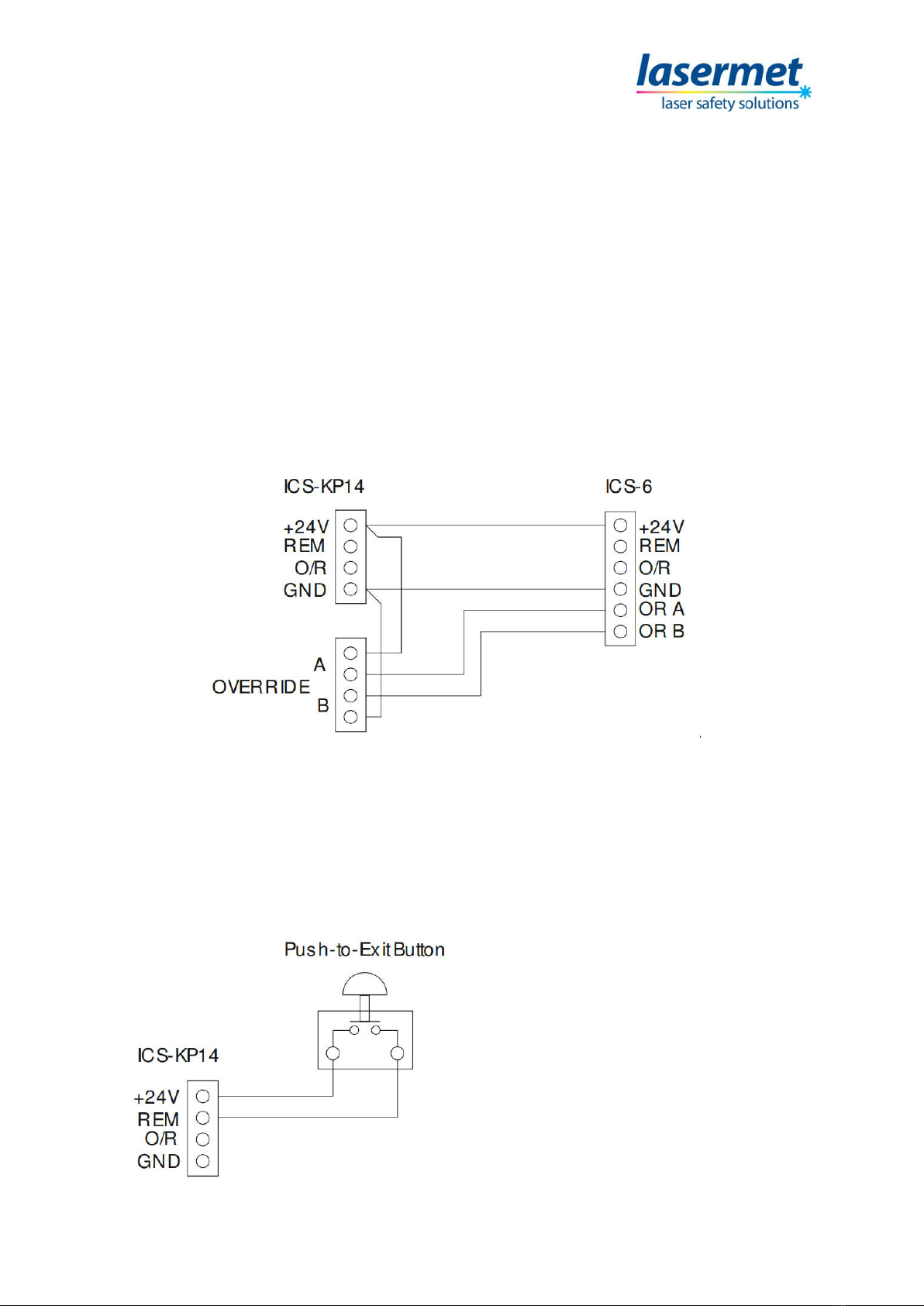
Connecting to ICS-6, overriding only the associated door
Three of the screw terminals of J8 inside the keypad: +24V, O/R and 0V are wired directly to the
corresponding terminals of J7 inside the ICS-6 using suitable copper low-voltage cable. The O/R
connection allows the ICS-6 to signal an override when the keypad is operated.
The jumper link J6 ‘OVERRIDE CONTROL’ is removed so that the ICS-6 only indicates that an override
is active but isn’t actually overridden itself.
The two override output contacts A and B on J6 in the keypad are wired across the two safety contacts
of the door switch. This is the contact which is closed when the door is closed. When the override is
activated the keypad override contacts will maintain the safety circuit when the door contacts open.
IMPORTANT!
Ensure the plug-in jumper link J6 ‘OVERRIDE CONTROL’ on the ICS-6 Main Circuit Board is removed
(set open) so that the keypad can activate the override indications in the ICS-6 without actually
overriding it. If this link is left closed all the other doors in the system will be overridden at the same
time.
ICS-KP14 Instruction Manual
01850-53-000 Page 10 of 18 Issue 3 19 January 2021
Connecting to ICS-6, overriding all doors
Connections are made inside the keypad to produce a dual channel override signal to the ICS-6, as
follows:
Two of the screw terminals labelled +24V and 0V on J7 inside the ICS-6 should be wired directly to the
corresponding terminals of J8 inside the keypad using suitable copper low-voltage cable. The jumper
link J6 ‘OVERRIDE CONTROL’ may be left open or closed.
Then a jumper wire is put inside the keypad from J8 +24V to one of the A terminals of J6, and another
jumper from J8 GND to one of the B terminals of J6. The other ‘A’ terminal of J6 goes to the ‘OR A’
terminal of J7 inside the ICS-6, and the other ‘B’ terminal of J6 goes to the ‘OR B’ terminal of J7 inside
the ICS-6. Make sure the connections are not transposed- the OR A terminal of J7 in the ICS-6 must be
fed through the A terminals of J6 in the keypad and thence to +24V, and the OR B terminal through
the ‘B’ terminals of J6 to 0V (GND).
5.2 Internal Door Release
It is usual to provide an internal door release pushbutton to allow persons within the controlled area
to exit the area without tripping the laser. The pushbutton should be equipped with a contact which
closes when the button is pressed (NO). The pushbutton is connected across the +24V and REM
terminals of J8 inside the keypad.
When the Push-to-Exit button is pressed the
keypad will operate in exactly the same way as
it does when a valid code is keyed.
Ce manuel convient aux modèles suivants
1
Table des matières
Autres manuels Lasermet Clavier


