LAPP PROFINET ETHERLINE ACCESS PNF04T Manuel utilisateur

Quick Start Guide PROFINET switch 4/8/16 port
Version
1en
as of FW 1.08
www.lappkabel.com/activenetworkcomponents

Quick Start Guide PROFINET switch 4/8/16 port2
Contents
1. Safety instructions 3
2. Introduction 4
3. Preparing the PROFINET switch 5
4. Planning of the GSDML files 6
5. Setting the port properties 7
6. Topology detection 7
7. Assign the PROFINET switch a name 8
8. Media Redundancy Protocol (MRP) 9
9. Diagnosis and configuration via the web interface 10
10. Switch diagnosis and settings 12
11. Port mirroring 12
12. Statistics 13
13. Agents 14
14. SNMP 15
15. Setting the time 16
16. Resetting to factory settings 17
17. Firmware update 17
18. LED status information 18
19. Button functions 18
20. Technical data 19

Quick Start Guide PROFINET switch 4/8/16 port 3
1. Safety instructions
Target audience
This description is only intended for trained personnel qualified in control and automation
engineering who are familiar with the applicable national standards.
For installation, commissioning, and operation of the components, compliance with the instruc-
tions and explanations in this operating manual is essential. The specialist personnel is to ensure
that the application or the use of the products described fulfills all safety requirements, including
all applicable laws, regulations, provisions, and standards.
Intended use
The device has a protection rating of IP 20 (open type) and must be installed in an electrical
operating room or a control box/cabinet in order to protect it against environmental influences.
To prevent unauthorized operation, the doors of control boxes/cabinets must be closed and
possibly locked during operation.
The consequences of improper use may include personal injury to the user or third parties, as
well as property damage to the control system, the product, or the environment. Use the device
only as intended!
Operation
Successful and safe operation of the device requires proper transport, storage, setup, assembly,
installation, commissioning, operation, and maintenance.
Operate the device only in flawless condition. The permissible operating conditions and
performance limits (technical data) must be adhered to.
Retrofits, changes, or modifications to the device are strictly forbidden.

Quick Start Guide PROFINET switch 4/8/16 port4
2. Introduction
This Quick Start Guide explains the basic settings for the initial commissioning of PROFINET
switches for use in a PROFINET project.
You can find further information in the manual. You can find this under www.lappkabel.com/
activenetworkcomponents or scan the QR code directly.
P1 — P4:
For PROFINET devices
or other
Ethernet devices
Voltage supply Operation LEDs (see page 18)
FCN:
Function
button
RST:
Reset button
Voltage supply
Operation LEDs (see page 18)
P1 — P16:
For PROFINET devices
or other
Ethernet devices
Voltage supply Operation LEDs (see page 18)
FCN:
Function
button
RST:
Reset button
FCN:
Function
button
RST:
Reset button
SCAN
QR CODE
TO GET
MANUAL
P1 — P8:
For PROFINET
devices or other
Ethernet devices
Quick Start Guide PROFINET switch 4/8/16 port 5
3. Preparing the PROFINET switch
3.1 Connection
The PROFINET switch must be supplied with 24 V DC at the wide range input
18 – 30 V DC via the provided connector plug.
The RJ45 sockets “P1 – P4” (4 port switch), “P1 – P8” (8 port switch) and
“P1 – P16” (16 port switch) serve the connection of the network participants
(PROFINET or Ethernet).
SCAN
QR CODE
TO GET
GSDML
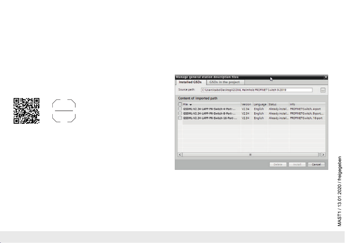
3.2 Install GSDML file
Please download t
he GSDML file
under www.lappkabel.com/activenetworkcomponents
or scan the QR code.
Note: The housing of the PROFINET switch is not grounded. Please connect the functional
grounding connection (FG) of the PROFINET switch correctly with the reference potential.

Quick Start Guide PROFINET switch 4/8/16 port6
4. Planning of the GSDML files
Following installation, the PROFINET switch can be found in the hardware catalog under
“Other field devices
g
PROFINET IO
g
Network Components
gLAPP GmbH g
LAPP PN
switch”. Add the “PROFINET Switch, 4 port”, “PROFINET Switch 8 port” of “PROFINET Switch,
16 port” device to the project and connect it with your PROFINET network.
By calling up the object properties, you must assign the PROFINET switch a unique PROFINET
name and check the IP address for plausibility in the project.
Important: The real device must later be assigned the same name as in the project.
See also Chapter 6.
Quick Start Guide PROFINET switch 4/8/16 port 7
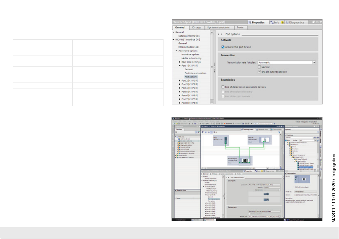
5. Setting the port properties
Each port of the PROFINET switch can be individually configured.
Transfer medium/duplex:
“Activate” The port can be switched off here. This option is
recommended when the port shouldn’t be used.
Unauthorized trespass into the network is prevented.
Transmission rate
“Automatic”
The port synchronizes itself automatically with the
communication partner (auto-negotiation).
“TP 100 Mbps”,
Transmission rate full duplex
Fixed specification of the transmission rate. This
option is recommended when connecting PROFINET
IO devices.
Monitor Send a diagnosis by Link Down
Enable autonegotiation Automatic recognition of the transmission speed and
the cable type (cross or patch cable)
6. Topology detection
The PROFINET switch supports the mechanisms for neighborhood detection (LLDP). With
this function it is possible to detect the topology of a PROFINET network, or to specify it for
purposes of checking for the correct structuring by the configuration.
If the topology was prescribed in the configuration, neighboring devices can also be assigned
the PROFINET name in the event of the replacement of a device.
This makes the recognition and testing of the network topology and the “device exchange in
operation” of connected PROFINET participants possible.

Quick Start Guide PROFINET switch 4/8/16 port8
7. Assign the PROFINET switch a name
When the configuration of the PROFINET switch has been completed in the hardware
configurator of the engineering tool, it can be loaded into the PLC.
In order that the PROFINET switch can be found by the PROFINET controller, the PROFINET
device name must be assigned to the PROFINET switch. To this purpose, use the function
“Assign device name”, which you can access in the Online menu with the right mouse button
when the PROFINET switch is activated.
With the “Update list” button, the network can be browsed for PROFINET participants. The
PROFINET device name can be assigned to the device with “Assign name”.
The clear identification of the PROFINET switch is ensured here by the MAC address of the
device. The MAC address of the device can be found on the device front of the PROFINET
switch.
The IPSet tool, which can be downloaded at no charge from the LAPP website, can also be
used to set the PROFINET name.
If the DP/PN Coupler has been assigned the correct name, it is recognized by the PLC and
configured. If configuration has taken place correctly, the PROFINET “BF” LED should be off.
If configuration has also taken place correctly on the PROFIBUS side, the PROFIBUS “BF” LED
should also be off. When both network sides have been configured appropriately (number and
size of the IO areas agree), the “SF” LEDs on both sides should also be out on both sides and
data transmission be underway.
SCAN
QR CODE
TO GET
IPSET

Quick Start Guide PROFINET switch 4/8/16 port 9
8. Media Redundancy Protocol (MRP)
The PROFINET switch supports the optional media redundancy protocol (MRP) as MRP client.
MRP enables ring wiring, which also makes operation of the PROFINET network possible in
the event of the failure of a cable or of a participant.
There must be at least one MRP master (e.g. the CPU) in an MRP ring. All other participants
of the ring are then MRP clients.
In order to assign the PROFINET switch to an MRP ring, the “Client” media redundancy role
must be set for the “Media redundancy” option under “Properties/General”.
Important: If ring wiring is produced without the MRP roles being configured for all devices
involved, this can result in functional disruptions of the PROFINET network!

Quick Start Guide PROFINET switch 4/8/16 port10
9. Diagnosis and configuration via the web interface
The web interface is also accessible under the IP address assigned to the PROFINET switch in the PROFINET network.
When the web interface is first called up, the password of the “admin” user is the serial number of the device. The serial number is indicated on the right housing side part (e.g. “50001234”).
It is absolutely necessary to assign a new password following the first login:
Ce manuel convient aux modèles suivants
2
Table des matières
Autres manuels LAPP Changer


