KWB Easyfire Manuel utilisateur

The Biomass Heating System
We Provide Energy for Life!
Original manual
Operation
Pellet Heating System
KWB Easyfire 8-35 kW

Table of Contents (Index)
1 General 7
1.1 About this Manual 7
1.2 Explanation of the Formatting 7
1.3 Please note 8
2 Overview 10
2.1 System components 10
2.2 Safety elements 10
2.3 Fire safety regulations 11
3 Operating fundamentals 12
3.1 Main switch 12
3.2 Introduction to the KWB Comfort 3 control 12
3.2.1 Introduction 12
3.2.2 Menu navigation 13
3.2.3 Changing values 13
3.2.4 Operating example 13
3.3 Regulating the domestic hot water 14
3.4 Regulating the room temperature 15
3.5 Regulating the fuel supply 15
3.5.1 Specifying the filling times (suction systems) 15
3.6 The system in the yearly cycle 15
3.6.1 Shutting down the system 16
3.6.2 Restarting the boiler after periods of standstill 16
3.7 Reacting to problems 16
3.7.1 Setting the date and time of day 17
3.7.2 Calling customer service 17
3.7.3 Additional temporary setting options 17
4 Operating the analogue remote control unit 18
5 Regular tasks 19
5.1 Fuels 19
5.1.1 From local standards to the EN14961 19
Table of Contents (Index)
2B KWB Easyfire EN, 05.2011

5.1.2 Filling / refilling with fuel 19
5.1.3 Emptying the fuel storage room 20
5.2 Ash container 20
5.2.1 Removing the ash container 20
5.2.2 Emptying the ash container 20
5.2.3 Attaching the ash container again 21
6 The commands of the KWB Comfort 3 control 22
6.1 Overview 22
6.2 System on/off 22
6.3 Room temperature 23
6.4 Party operation 23
6.5 Heating circuits 23
6.5.1 Heating programs 24
6.5.2 Changing heating times 24
6.5.3 Holiday program 26
6.6 Boiler 26
6.6.1 DHWC program 26
6.6.2 Charging times 27
6.6.3 DHWC temperature 27
6.6.4 Holiday program 28
6.6.5 Fast charging 28
6.7 Buffer 28
6.7.1 Buffer program 28
6.7.2 Charging times 29
6.7.3 Buffer temperature 30
6.8 Operational state 30
6.8.1 Boiler 30
6.8.2 Heating circuits 32
6.8.3 Boiler 33
6.8.4 Buffer 34
6.8.5 Fuel extractor (worm) 35
6.8.6 Fuel extractor (suction system) 35
6.8.7 Second boiler 37
6.8.8 Power measurement 37
6.9 Date / Time 38
Table of Contents (Index)
B KWB Easyfire EN, 05.2011 3

6.10 Pellet suction system 38
6.11 Customer service 39
6.12 Alarms 39
6.12.1 Displays 39
6.12.2 Log 40
6.12.3 Statistics 40
6.12.4 Rectifying 40
6.13 Boiler program 40
6.13.1 Changing times 40
6.14 Extensions 41
6.14.1 Comfort SMS 41
6.15 Expert level 41
7 Maintenance 42
7.1 Standards for maintenance 42
7.1.1 Weekly visual inspection 42
7.1.2 Monthly inspections 42
7.1.3 Additional regular work 42
7.1.4 Professional maintenance 43
7.1.5 Forms 43
7.2 Maintenance intervals 46
7.2.1 Reasons for on-going, professional maintenance service 46
7.3 Before you begin 46
7.4 Maintenance steps 47
7.4.1 Cleaning the surfaces 47
7.4.2 Checking the combustion chamber 47
7.4.3 Emptying the ash container 47
7.4.4 Cleaning the burner plate and ignition pipe 48
7.4.5 Flue gas collecting chamber and induced draught fan 49
7.4.6 Cleaning the head section for suction conveyor system 49
7.4.7 Cleaning the fill level sensor in the suction tank 50
7.5 Interruption of operation 50
8 Troubleshooting 51
8.1 Reacting to alarms 51
8.1.1 Displaying the alarm log 51
Table of Contents (Index)
4B KWB Easyfire EN, 05.2011

8.1.2 Displaying the alarm statistics 51
8.2 The alarm list 52
8.2.1 Alarm 00 – The control system is not completely adjusted 52
8.2.2 Alarm 01 – The memory module is faulty 52
8.2.3 Alarm 02 – Electronic defect on the digital inputs 52
8.2.4 Alarm 03 – The time must be reset 52
8.2.5 Alarm 04 – The maintenance interval has elapsed. Notify customer serv-
ice.
52
8.2.6 Alarm 05 – Safety thermostat! Boiler overheating! 53
8.2.7 Alarm 06 – Main drive motor is overheated! 53
8.2.8 Alarm 07 – The ignition does not function! 53
8.2.9 Alarm 08 – The fuel storage bunker is empty! Please refill! 54
8.2.10 Alarm 09 – Flue-gas sensor values not plausible! 54
8.2.11 Alarm 10 – The return flow boost does not function! 54
8.2.12 Alarm 12 – Flue-gas temperature too low during operation 55
8.2.13 Alarm 13 – Temperature increase in the fuel supply, fire alarm! 55
8.2.14 Alarm 14 – The electronics have a temperature of 70 °C! 55
8.2.15 Alarm 15 – The flue-gas sensor is missing or is defective! 55
8.2.16 Alarm 16 – The flue-gas sensor cable is missing or is defective! 55
8.2.17 Alarm 17 – The boiler sensor is missing or is defective! 56
8.2.18 Alarm 19 –The ash container is not installed correctly! 56
8.2.19 Alarm 21 – Configuration error! The configuration last saved is active! 56
8.2.20 Alarm 22 – Flue-gas temperature too high during operation 56
8.2.21 Alarm 23 – The fuel storage container is empty! 56
8.2.22 Alarm 24 – Error on the sample probes system 57
8.2.23 Alarm 25 – Main drive speed too low! 57
8.2.24 Alarm 26 – Main drive speed too high 57
8.2.25 Alarm 27 – Boiler temperature not plausible! 57
8.2.26 Alarm 30 –The forward flow sensor of heating circuit 0 is missing or defec-
tive!
57
8.2.27 Alarm 31 – The room sensor of heating circuit 0 is missing or defective! 57
8.2.28 Alarm 32 –The outdoor sensor of heating circuit 0 is missing or defective! 57
8.2.29 Alarms 33 to 134 58
8.2.30 Alarms 135 to 151 – The sensor from the boiler x is missing or defective! 58
8.2.31 Alarms 152 to 185 – The sensor 1 (2) from the buffer x is missing or de-
fective!
58
8.2.32 Alarm 187 – Network error on the boiler module 2! 58
8.2.33 Alarms 188 to 203 – Network error on the heating circuit module x! 58
Table of Contents (Index)
B KWB Easyfire EN, 05.2011 5

8.2.34 Alarms 204 to 237 – Network error on the digital remote control unit x! 59
8.2.35 Alarm 238 – Fault in the heating circuit network 59
8.2.36 Alarm 239 – The boiler sensor on the second boiler is missing or is defec-
tive!
59
8.2.37 Alarm 240 – The negative pressure in the combustion chamber cannot be
regulated!
59
8.2.38 Alarm 241 – The negative pressure sensor is defective! 60
8.2.39 Alarm 242 – The oxygen sensor is missing or is defective! 60
8.2.40 Alarm 244 – Calibration error of the lambda probe 60
8.2.41 Alarm 246 – No flame detectable 60
8.2.42 Alarm 248 – The maintenance interval has elapsed. 60
8.2.43 Alarm 249 – The chimney sweep function is active 60
8.2.44 Alarm 250 – PCB revision and system number are not compatible 60
8.2.45 Alarm 251 – The emergency stop switch is pressed! 61
8.2.46 Alarm 253 – Speed of the PA fan is too low! 61
8.2.47 Alarm 254 – The speed of the induced draught fan is too low! 61
8.2.48 Alarm 255 – Error GSM module 61
9 Appendix 62
9.1 Efficient and low-emission operation 62
9.2 Stickers 62
9.2.1 Stickers on the switch bracket 62
9.2.2 Stickers on the front 63
9.2.3 Stickers on the rear side 63
9.2.4 Stickers on the blow-in nozzle 64
9.2.5 Stickers on the storage room 65
TTD-EF2 66
KE_KWB_EF2 68
Glossary 69
Keyword index 70
Table of Contents (Index)
6B KWB Easyfire EN, 05.2011

General
About this Manual
This manual contains all the required information für den Betrieb und die Bedienung. The chap-
ter sequence corresponds to the recommended workflow. For further queries please contact
your sales partner or KWB Customer Service.
The KWB – Kraft und Wärme aus Biomasse GmbH including their country representatives and
authorised competence partners are hereinafter referred to as KWB in short.
The KWB Managing Directors Stephan Jantscher and Erwin Stubenschrott
Our objective is to constantly improve our products and manuals –
we would appreciate your comments and suggestions.
You can find all contact data on the back side of this document.
Original manual – Subject to change. No responsibility accepted for errors and
omissions!
Explanation of the Formatting
We use different symbols for the requirements, the actual work steps and the results
mRequirement
4Work step
9Result
1
1.1
1.2
Work steps
General 1
B KWB Easyfire EN, 05.2011 7

Keywords at the left of the text columns help you identify the contents of the paragraph.
You can recognise a reference to another section in this document by an arrow and the page
number in square brackets. Example: About this Manual [► 7]
Please note
Grading of the safety instructions
KWB protects you in the documents with the most internationally secure and modern warning
system. Signal words, colours and texts change with increasing danger:
NOTICE General information
We use this display to indicate and describe important information.
CAUTION Beginning hazard
We use this display to indicate and describe beginning hazards. If these stated
hazards are not observed, injuries, property damage and environmental
damage can occur.
WARNING Medium hazard
We use this display to indicate and describe hazards. If this warning is not ob-
served, severe or fatal injuries can occur.
DANGER Serious hazard
We use this display to indicate and describe serious hazards. Disregarding
this warning will lead to serious or fatal injuries!
General safety instructions
•Do not alter the system in any way!
• Close all provided covers before you place the system into operation!
• Unplug the connector before you perform any service or open the control!
• Always disconnect the power supply before you enter the fuel storage room.
NOTICE Proper installation by specialists
mThe entire installation, integration and commissioning of the heating system
may only be carried out by expert specialists of KWB or their partners.
4All the work must conform to the specifications stated in the KWB manuals
and local regulations.
Comply with the safety instructions
NOTICE Please comply with the safety instructions
Your system has been tested for safety and it satisfies the applicable standards,
directives and regulations.
Failure to comply with the safety instructions or improper use poses danger of
material damage. In addition, failure to comply with the safety instructions or
improper use also poses a life-threatening hazard!
Side text
Cross referen-
ces
1.3
1.3.1
1.3.2
1General
Please note
8B KWB Easyfire EN, 05.2011

Please read and follow the manual
NOTICE Please read this manual carefully before installation or commissioning!
Compliance with this manual and proper installation or commissioning is a pre-
requisite for warranty provided by the KWB .
4If something is not clear, please look it up in this manual or contact the
KWB customer service.
Legal
Intellectual Property
© 2010 KWB – Kraft und Wärme aus Biomasse GmbH
All catalogues, brochures, diagrams, drawings, manuals and control and adjustment pro-
grammes etc. are protected as intangible property and always remain the intellectual property
of KWB. Any use, reproduction, distribution, publication, processing and/or other transfer to
third parties requires the prior written consent of KWB.
When operating the contractual goods, the installation, operating and other technical regula-
tions and instructions from KWB must be strictly observed and adhered to.
NOTICE Warranty
mThe manufacturer’sKWB warranty specifies proper installation and commis-
sioning of the system as the prerequisite. Defects and damage due to im-
proper installation, commissioning and operation are excluded from the
warranty.
4The manufacturer’s instructions must be complied with to ensure proper
system function. Knowledge of the manuals is a prerequisite.
4Use only original parts or parts that have been expressly approved by the
manufacturer.
4If something is not clear, please look it up in this manual or contact the
KWB customer service.
Liability / Warranty
Any change and / or modification of the contractual goods or in the operation of the contractual
goods not expressly authorised by KWB in writing or their operation in conjunction with other
devices or accessories the compatibility of which has not been expressly confirmed by KWB,
any inappropriate operation/use (e.g. the use of fuels and/or water not in accordance with
standards which do not correspond to VDI 2035 or ÖNORM H 5195-1; inappropriate and / or
excessive use) leads to the exclusion of the warranty. Any liability or warranty for compatibility
of the contractual goods with other products, systems, plants or parts, as well as the suitability
thereof for a specific use are excluded unless otherwise expressly permitted in writing.
Intended use
KWB boilers heat water for central heating systems. The application, operation, maintenance
and repair of KWB systems must, without exception, be performed as described in the instruc-
tions.
The following fuels are prescribed without exception.
Any other use is regarded as NOT designated. Resulting damage is the liability of those operat-
ing the system and users.
1.4
General 1
Legal
B KWB Easyfire EN, 05.2011 9
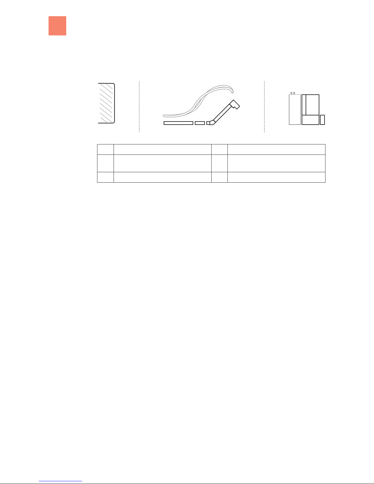
Overview
System components
21 53 4
Schematic diagram of the system elements
1 Fuel storage room 4 Burner with heat exchanger and control
2 Conveyor system:
Suction conveyor system and/or worm
5 Ash container
3 Hopper (optional)
Safety elements
We have taken the following measures in order to maximize the safety of our systems.
Cellular wheel sluice
The cellular wheel sluice, developed by KWB as backfire-protection device ( according to
TRVB H118), prevents fire from being able to spread back to the fuel feed from the combustion
chamber.
Negative pressure monitoring
The continuous monitoring and control ensures the negative pressure in the combustion cham-
ber.
Photocell monitoring
Direct photocell monitoring of the combustion chamber allows the control to be able to react
significantly faster because it does not have to wait for a temperature change at a measure-
ment point.
Safety thermostat
This system switches off the heating system if the boiler temperature should increase to 95 C.
Sensor for flue gas temperature
In conjunction with the photocell, the sensor for flue gas temperature monitors the fill level and
the ignition procedure in the combustion chamber.
Photocell
In conjunction with the sensor for flue gas temperature, the photocell monitors the fill level and
the ignition procedure in the combustion chamber.
Lambda control system
The lambda control system adapts the combustion to various fuel qualities.
2
2.1
2.2
2Overview
10 B KWB Easyfire EN, 05.2011
Autres manuels pour Easyfire
1
Table des matières
Autres manuels KWB Système de chauffage


